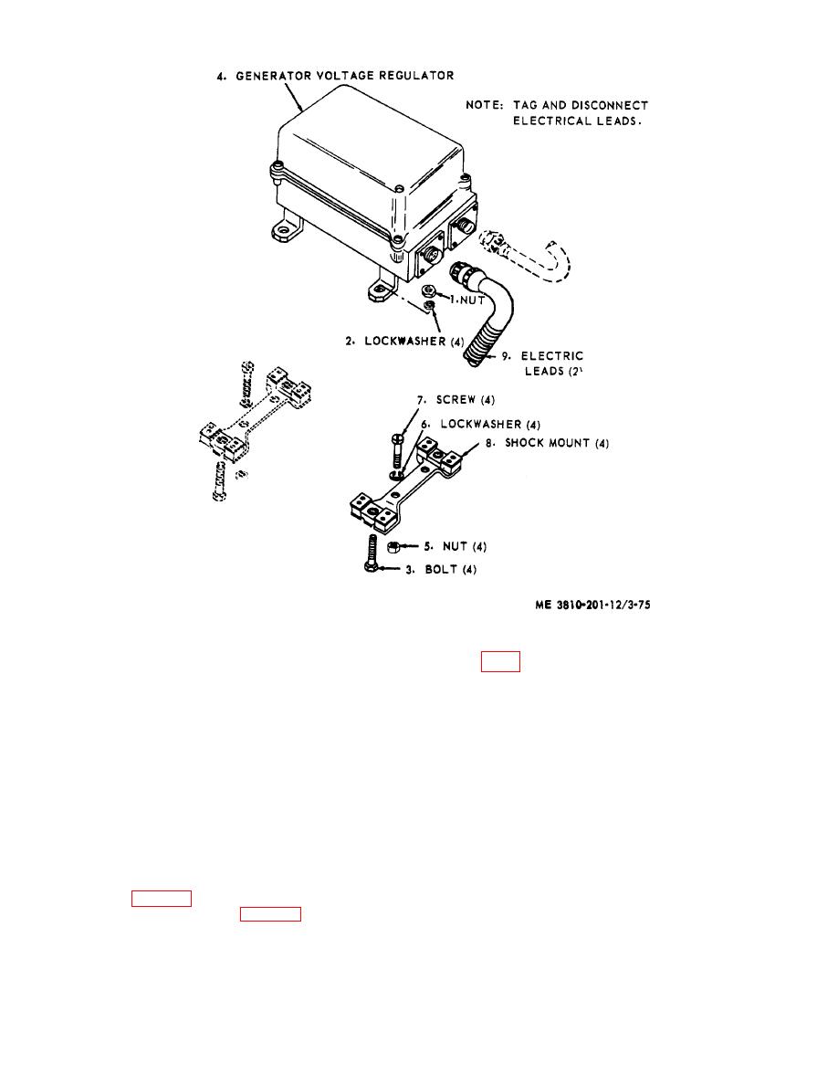
Figure 3-75. Generator voltage regulator and shock mounts, removal and installation.
install in a manner similar to that described in (1)above.
b. Cleaning, Inspection, and Repair.
(3) Remove capscrews (4), lockwashers,
nuts, and receptacle (slave) electrical connector.
(1) Clean relay solenoid with a rag dampened
(4) Install by reversing steps (1) through (3)
in an approved cleaning solvent and dry thoroughly.
above.
(2) Visually inspect mounting hardware for
b. Cleaning, Inspection, and Repair.
excessive wear or stripped threads, electrical leads for
(1) Clean all parts with an approved cleaning
loose terminals, bare wire, or frayed insulation, and test
solvent and dry thoroughly.
relay for proper operation by placing source of 24 vdc
(2) Visually inspect hardware for excessive
power across terminals and listen for solenoid
wear or stripped threads, electrical leads for loose
movement.
terminals, bare wire, or frayed insulation, and receptacle
(3) Repair by replacing defective hardware,
for proper mating with plug electrical connector.
electrical lead, or defective relay solenoid.
(3) Repair by replacing defective hardware,
3-89. Receptacle (Slav.) Electrical Connector
electrical leads, or receptacle.
a. Removal and Installation.
3-90. Lubricating Oil Pressure Transmitter
(1) Remove capscrew, lockwasher, and
a. Removal and Installation.
ground cable (fig. 3-79).
(2) Remove nut (7, fig. 3-77) and electrical
lead (8) then remove clip and grommet (fig.
3-89


