c. Inspection. Visually inspect insulation or looms
for cracks or fraying. Closely examine lead or harness
at all points where passage is over rough or sharp
edges, or through holes without grommet protection.
Examine lead terminals for security to lead or terminal
post of junction box and accessory. Carefully trace
leads by refering to applicable portion of wiring diagram
leads or harness.
d. Replacement.
(1) Individual leads will be replaced by
disconnecting at both terminal points, and installing a
new lead of exactly the same size wire. Be sure that
end terminals are secure on lead and terminal post, and
that markers are removed from old lead and installed on
ends of new lead, or that new markers are prepared and
installed in a similar manner.
(2) Individual leads within a harness may be
replaced by cutting a length of wire lead as long as the
defective lead, taping it to outside of harness at frequent
intervals, installing end terminals and connecting to
proper terminals. Be sure that protruding ends of old
lead are cut off as close to harness as practical, and that
markers are removed from old lead and installed on
both ends of the substitute lead.
(3) When there are two or more defective
leads within a harness, the harness should be replaced.
Tag terminals, identifying lead color or marker number,
and disconnect and remove harness.
Install new
harness, making sure that all leads are correctly
positioned and securely fastened to terminals.
Caution: Never remove, or install,
leads to alternator while battery
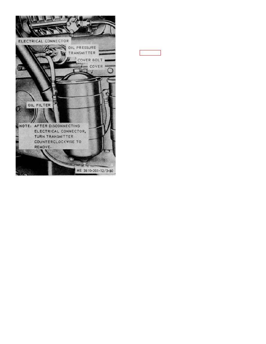
Figure 3-80.
Lubricating oil pressure transmitter
cables are installed. Disconnect and
removal and installation.
tie battery cables back to prevent
low voltage test lamp. Leads within a harness may be
alternator, or transistors in voltage
tested similarly by tagging and disconnecting one end of
regulator are easily damaged by
a harness, moving loose end closer to fixed end for
flash current.
ease in reaching terminals by probes of multimeter or
test lamp.
3-93


