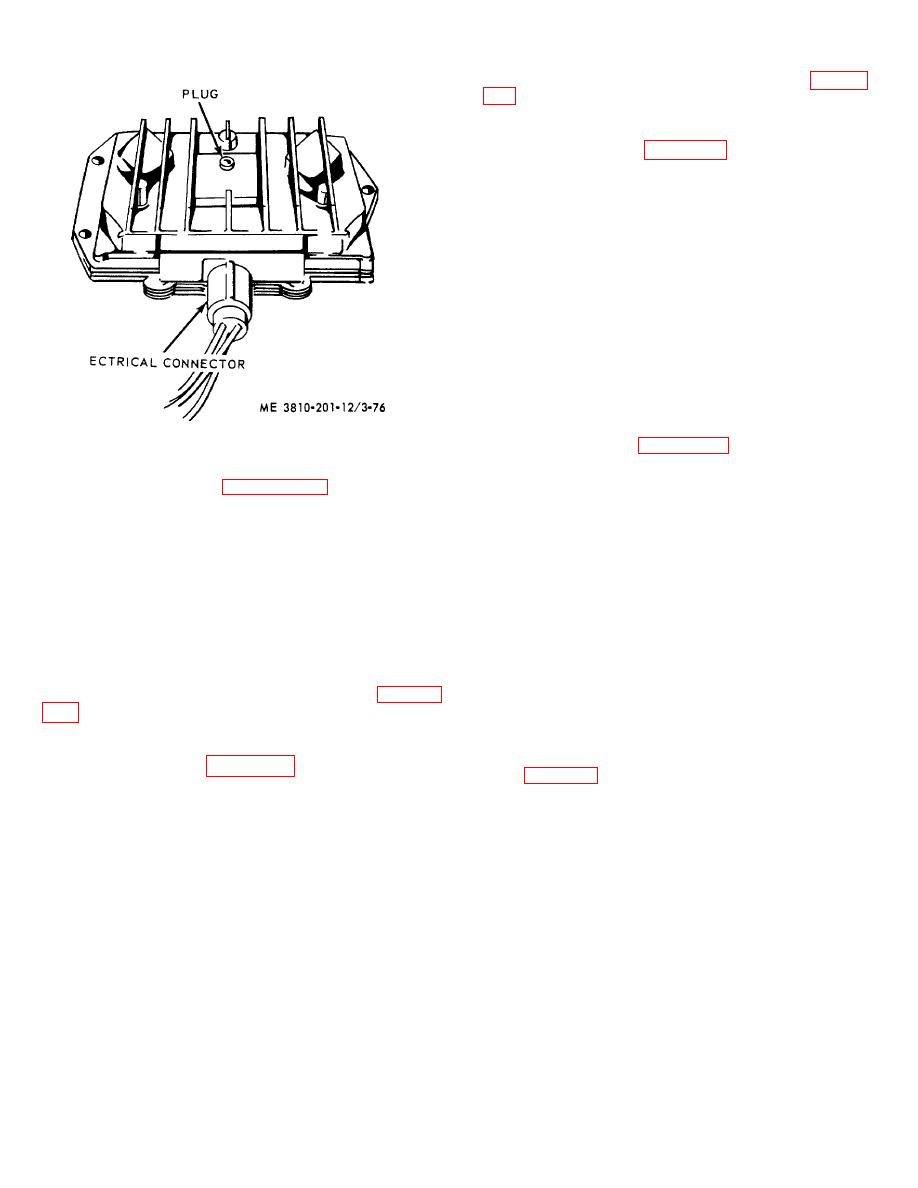
(3) Repair by repairing electrical lead (para 3-
3-92. Water High Temperature Switch
a. Removal and Installation.
(1) Refer to figure 3-81, tag and disconnect
three electrical leads, then remove water high
temperature switch from engine model 687C-18-
ES. Install in reverse order.
(2) Remove water high temperature switch
from engine model D333TA in a manner similar to that
given in (1) above.
b. Cleaning, Inspection, and Repair.
(1) Clean all parts in an approved cleaning
solvent and dry thoroughly.
(2) Visually inspect electrical leads for loose
connections or frayed insulation, inspect switch for
cracked or dented housing.
(3) Repair by replacing defective lead or
switch.
3-93. Low Oil Pressure Switch
a. Removal and Installation.
Figure 3-76. Alternator voltage regulator, adjustment,
(1) Refer to figure 3-82, tag and disconnect
removal, and installation.
three electrical leads, then remove low oil pressure
switch from engine model 687C-18-ES.
Install in
(1) Refer to figure 3-80 and remove
reverse order.
lubricating oil pressure transmitter from engine model
(2) Remove low oil pressure switch from
687C-18-ES. Install in reverse order.
engine model D333TA in a manner similar to that given
(2) Remove
lubricating
oil
pressure
in (1) above.
transmitter from engine model D333TA in a manner
b. Cleaning, Inspection, and Repair.
similar to that given in (1) above.
(1) Clean all parts in an approved cleaning
b. Cleaning, Inspection, and Repair.
solvent and dry thoroughly.
(1) Clean all parts with an approved cleaning
(2) Visually inspect electrical leads for loose
solvent and dry thoroughly.
connections or frayed insulation, inspect switch for
(2) Visually inspect electrical connector for
cracked or dented housing.
defective connections or frayed lead, inspect transmitter
(3) Repair by replacing defective lead or
for defective threads, cracked housing, or other defect.
switch.
(3) Repair by repairing electrical lead (para 3-
3-94. Overspeed Governor (On Engine Model
687C-1 8-ES)
3-91. Water Temperature Transmitter
a. Removal and Installation.
a. Removal and Installation.
(1) Disconnect and remove tachometer drive
(1) Refer to figure 3-81, disconnect electrical
cable (fig. 3-83), then tag and disconnect two electrical
connector, and remove water temperature transmitter
leads.
from engine model 687C-18-ES. Install in reverse
(2) Remove four capscrews, lockwashers,
order.
and flatwashers securing overspeed governor to engine
(2) Remove transmitter from engine model
front cover, then remove governor.
D333TA in a similar manner to that given in (1) above.
(3) Install in reverse order.
b. Cleaning, Inspection, and Repair.
b. Cleaning and Inspection.
(1) Clean all parts in an approved cleaning
(1) Clean all metal parts with an approved
solvent and dry thoroughly.
cleaning solvent and dry thoroughly. Wipe microswitch
(2) Visually inspect electrical connector for
with a rag dampened in solvent.
defective connections or frayed lead, inspect 3-90
(2) Visually inspect mounting hardware
transmitter for defective threads, cracked housing, or
other defect.
3-90


