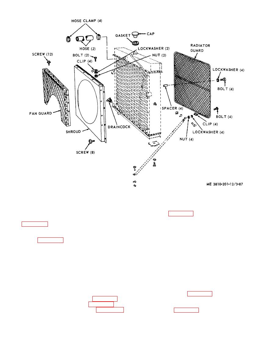
Figure 3-87. Fan guard and shroud (engine model 687C-18-ES), removal and installation.
(d) Install in reverse order.
(c) Repair by straightening bends,
welding cracks, or replacing defective hardware.
(2) Disassembly aid ?reassembly. Refer to
c. Fan Idler Pulley (Engine Model D333TA).
view D of figure 3-92 and disassemble fan hub.
Reassemble in reverse order.
(1) Removal and installation. Refer to view A
(3) Cleaning, inspection, and repair.
or figure 3-92 and remove fan idler pulley. Install in
reverse order.
(a) Clean all parts in an approved
(2) Disassembly and reassembly. Refer to
cleaning solvent and dry thoroughly.
(b) Visually inspect all parts for damage
view B of figure 3-92 and disassemble fan idler pulley.
Reassemble in reverse order.
or defect. Inspect seal for deterioration, bearings for
(3) Cleaning, inspection and repair.
wear or scoring, and mounting hardware for burs or
stripped threads.
(a) Clean all parts in an approved
(c) Repair by replacing damaged,
cleaning solvent and dry thoroughly.
(b) Visually inspect all parts for damage
defective, or worn parts.
or defect.
(c) Repair by replacing damaged or
3-103. Fan Belt
defective parts.
a. Removal and Installation.
d. Fan Hub.
(1) From engine model 687C-18-ES.
(1) Removal and installation.
Refer to view A of figure 3-21, loosen adjustment screw,
then remove belt from pulleys. Install in reverse order.
(2) From engine model D333TA. Refer
to view A of figure 3-92, loosen adjustment screw,
remove fan hub.
3-100


