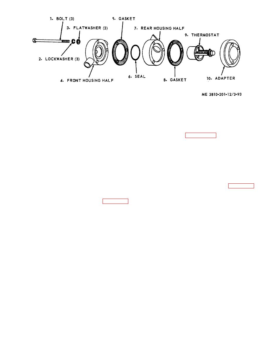
Figure 3-93. Thermostat housing, disassembly and reassembly.
Section XV. ENGINE CLUTCH
defective part, or defective mounting hardware.
3-107. General
c. Adjustment.
(1) Refer to paragraph 3-9 for instructions on
The clutch, when engaged, transfers power from engine
engine clutch adjustment.
to power takeoff output shaft, which actuates the
(2) Adjust lever and linkage by removing pins
operating mechanisms. A drive chain connects the
from clevises, and turning each clevis clockwise to
engine drive sprocket, working off the output shaft, to
shorten, counterclockwise to lengthen, until operator's
the main drive sprocket. The clutch is controlled,
control lever is properly positioned on quadrant when
through adjustable linkage, from the operators cab. An
clutch is in the engaged or disengaged position.
auxiliary control lever is located on the power takeoff
housing. The engine clutch requires adjustment if it will
3-109. Auxiliary Clutch Lever
not pull the load, heats, or the operating lever jumps out
of engagement.
3-108. Clutch Lever and Linkage
remove capscrew and lockwasher from lever, then
remove lever from crossbar. Install in reverse order.
b. Cleaning, Inspection, and Repair.
(1) Clean lever and mounting hardware in an
and remove clutch lever and linkage. Install in reverse
approved cleaning solvent and dry thoroughly.
order.
(2) Visually inspect lever for bend, crack, or
b. Cleaning, Inspection, and Repair.
excessive wear. Inspect hardware for burs, or stripped
(1) Clean all parts in an approved cleaning
threads.
solvent and dry thoroughly.
(3) Repair by replacing worn or defective
(2) Visually inspect all parts for excessive
parts.
wear, burs, stripped threads, or other damage or defect.
(3) Repair by replacing a damaged or
3-105


