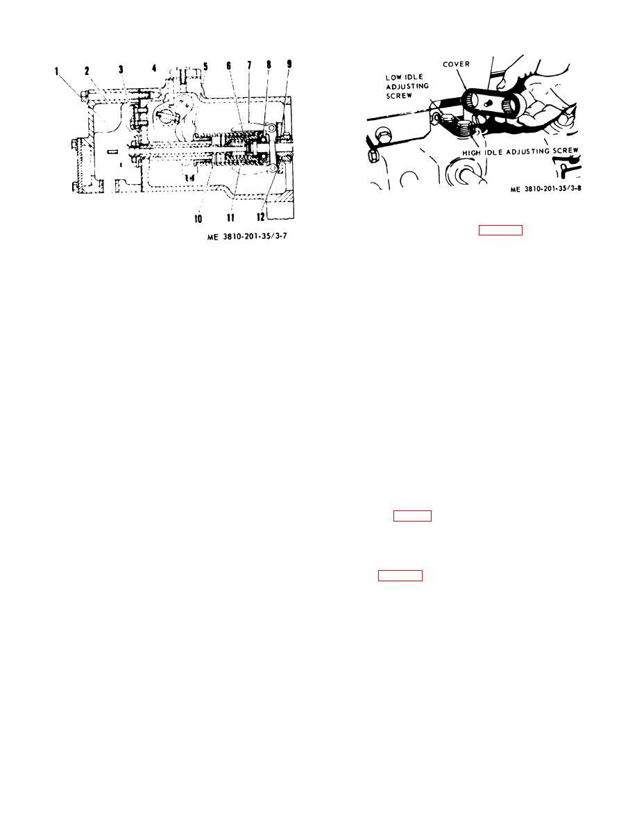
Figure 3-8. Governor high or low idle speed adjustment.
(2) Remove cover (fig. 3-8) from top of the
governor housing.
1
Shaft
7
Weights (2 rqr)
(3) Adjust the applicable adjusting screw by
2
Stop
8
Thrust bearing
turning it counterclockwise to decrease, or clockwise to
3
Spring
9
Fuel rack
increase the idle speed.
4
Lever
10
Spring
(4) When idle sped is correct, move governor
5
Shoulder
11
Spring seat
control lever to change speed, then return it to idle
6
Adapter
12
Bearing
position and recheck idle speed. Repeat the procedure
Figure 3-7. Engine governor, right side cross section
several times, until desired speed is obtained.
view
(5) When idle speed is correct, install cover
with serrated recesses over adjusting screws so that
weights (7) is always trying to decrease engine rpm.
proper adjustment will be retained. Secure cover with
Engine rpm is regulated when the centrifugal force of
the attaching screw.
weights balances the compression force of the governor
spring. When engine load is increased, engine rpm
d. Fuel Rack Setting.
decreases and the governor weights turn slower thus
losing part of their centrifugal force. Removal of this
CAUTION
force from spring allows spring to move seat (11),
An incorrectly adjusted fuel rack
connected to fuel rack (9), to an increased fuel position.
affects turbocharger operation.
With more fuel engine rpm increases, weights (7) swing
outward (as weights rotate faster) and the toes of
(1) Remove cover and gasket from rack
weights move thrust bearing (8), spring seat (11), and
bore of the accessory drive housing, and the cover from
fuel rack (9) toward a lesser fuel position. As the
rear of governor housing.
centrifugal force of weights again balances the force load
(2) Install rack setting gage over the front end
of compression spring, engine rpm will be the same as it
of fuel rack (fig. 3-9).
was before load was increased. As engine load
(3) Set gage to required setting for altitude.
decreases rpm increases, causing weights to rotate
(4) Move governor control lever to FULL
faster and swing outward moving toes away from thrust
LOAD position.
bearing and allowing spring to push fuel rack to a lesser
(5) When fuel rack is in FULL LOAD position,
fuel position. As the two forces again become balanced,
the stop (fig. 3-10) should just barely contact the spring.
engine rpm will be the same as it was before the load
decreased.
NOTE
If there is a shim, or shims, between
c. Adjustment of Idle Speed.
spring and governor housing, the
stop should contact (but not
(1) Remove service (hour) meter from front of
compress) the spring.
engine and install a tachometer drive with flexible
coupling to accurately check idle rpm.
WARNING
Do not remove, or install, the flexible
coupling while engine is running and
avoid possible injury.
AGO 20051A
3-12


