EMC 5-3810-206-35/30
1
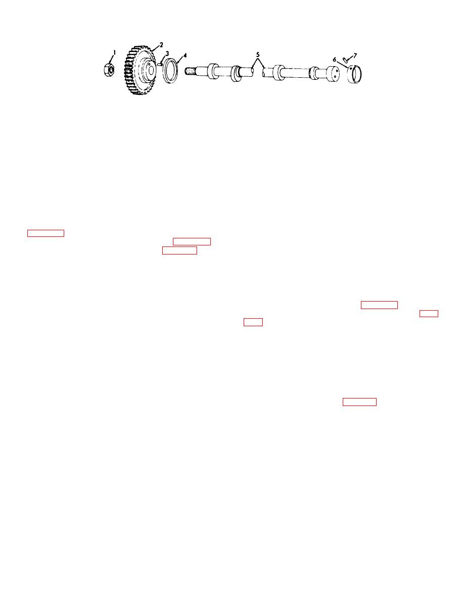
Nut
5
Camshaft
2
Drive gear
6
Sleeve bearings (7 rqr)
3
Pin
7
Pin
4
Thrustwasher
Figure 3-54. Camshaft for engine model 687C-18-ES exploded view.
be removed as a unit, after timing gear cover has been
NOTE
removed.
Use a narrow thickness gage leaf, not
3-51. Camshaft (Engine Model 687C18ES)
more than 1/L inch wide when
measuring this distance in order that
a. Removal and Installation.
accuracy may be assured. Replace
(1) Remove valve operating mechanism
bearings in a set of seven, if one is
worn more than 0.007 inch.
(2) Remove camshaft drive gear (para 3-30).
(3) Remove thrustwasher (4, fig. 3-54) from
(3) Repair by replacing worn or defective
components. Replace defective mounting hardware.
(4) Remove pin (3) from drive gear (2).
(5) Remove pin (7) from camshaft (5).
3-52. Camshaft (Engine Model D333TA)
(6) Remove camshaft (5) from crankcase.
(7) Remove sleeve bearings (6) from
a. Removal and Installation.
(1) Remove front cover (para 3-31).
(8) Install by reversing the procedures in
(2) Remove valve operating mechanism (para
steps (1) through (6) above.
b. Cleaning, Inspection, and Repair.
(1) Clean all parts and dry thoroughly before inspection
CAUTION
or installation.
(2) Use Vblocks to support camshaft, with paper strips
Use extreme care in withdrawing
soaked in oil to prevent scoring of journals. Attach a dial
camshaft from cylinder block so that
indicator at center journal and rotate camshaft while
cam lobes will not damage sleeve
reading the indicator.
bearings in block.
Reading must not be greater than 0.003 inch out of
round.
Measure each camshaft journal with a
(3) Remove nut (6, fig. 3-55) and retainer (5),
micrometer for wear. Measure between cam shaft and
then pull gear (4) off camshaft (1).
sleeve bearings for clearance of between 0.003 and
(4) Remove bolts (7), lock (8) and washer (3)
0.007 inch.
from shaft (1) Remove key (2) from shaft (1).
AGO 20051A
3-65


