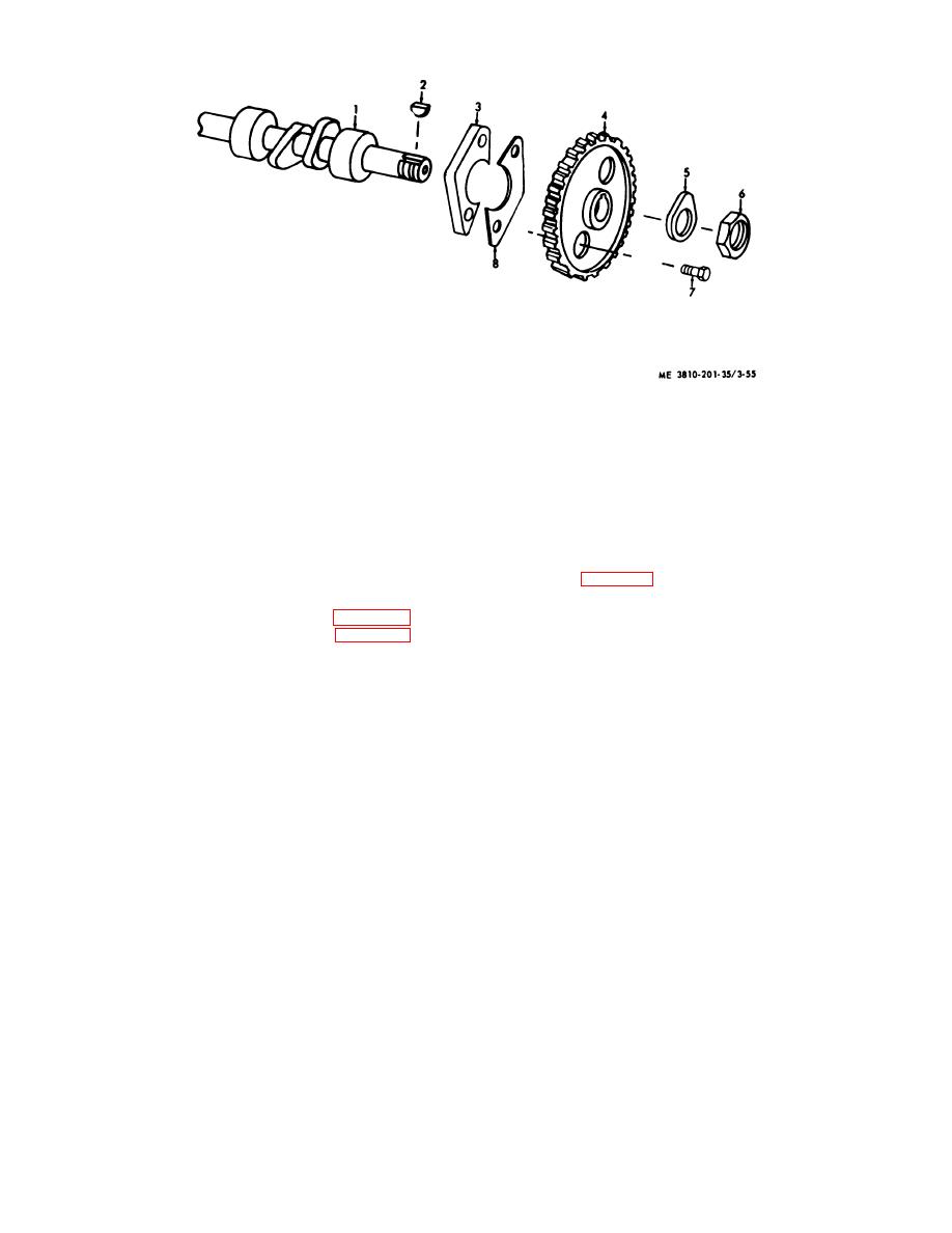
1
Camshaft
5
Retainer
2
Key
6
Nut
3
Washer
7
Bolt
4
Gear
8
Lock
Figure 3-55. Camshaft for engine model D333TA, exploded view.
b. Cleaning, Inspection, and Repair.
NOTE
(1) Clean all parts and dry thoroughly before
inspection or installation.
If camshaft bearings are to be
(2) Inspect camshaft journals and bearings for
removed from block continue as
wear (see table 1-1 for dimensional clearances and
follows:
tolerances). Inspect drive gear for chipped or broken
teeth. Inspect mounting hardware for burs or other
(5) Remove oil pan and plate (para 3-44).
damage.
(6) Remove flywheel housing (para 3-41).
(3) Repair by replacing all worn or defective
(7) Press bearings out of cylinder block.
components.
(8) Install camshaft by reversing the
procedures in steps (1) through (7) above.
Section XV. CYLINDER HEAD, VALVE, BLOCK, AND LINERS
3-53. General
3-54. Cylinder Head, Valve, and Liner (Engine Model
687C1 8ES)
a. Engine Model 687C-18-ES. Each cylinder of this
engine is an independent assembly which includes a
a. Removal and Installation.
cylinder head, liner, upper and lower jackets, and the
(1) Drain cooling system (TM 5-3810-201-12).
exhaust valve group. This design makes it possible to
(2) Drain crankcase and remove oil fill cap
service each cylinder independently.
(TM 5-3810-201-12).
(3) Remove valve cover and gasket (TM 5
b. Engine Model D333TA. This engine has the
3810-201-12).
conventional cylinder head, and cylinder block with liners.
(4) Remove fuel injectors (TM 5-3810-201-
The valve group is in the cylinder head.
12).
AGO 2051A
3-66


