b.
Adjustment.
at least the length of the crawler frame. This will place
the slack in the chain on top. Adjust as follows.
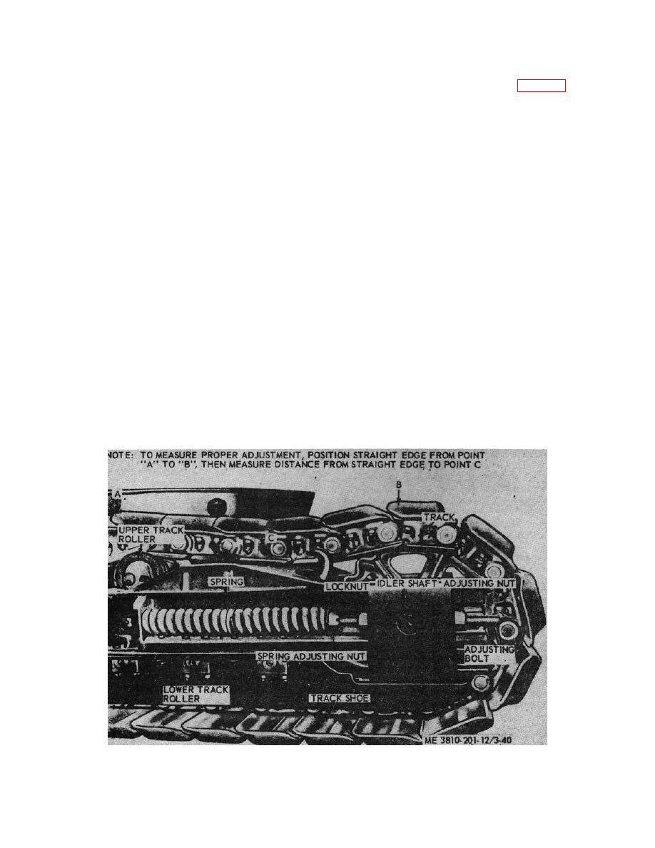
(1) Position a straight edge on track parallel
b.
Adjustment.
with frame, between upper roller (fig. 3-32) and high
point of track on top of drive sprocket. Measure
(1) Backoff locknuts on two eyebolts (fig. 3-
distance between straight edge and low point of track
31) (one on each side of sprocket) then, alternately turn
sag. This distance should be approximately 1 inches.
adjusting nuts, first on outside then on inside, in or out
If sag is more than 1 inch, loosen locknut on adjusting
until slack in propel chain can be raised approximately
bolt (on both sides of sprocket), then tighten adjusting
1 inches. Repeat on opposite side of frame for
nuts until sag is correct.
remaining propel chain. When adjustment is correct,
tighten locknuts to secure adjustment.
CAUTION
NOTE
Equalize turning of adjusting nuts,
so that idler shaft is parallel to front
When a new propel chain is installed,
axle. The teeth on idler sprocket
it must be adjusted tight (no slack),
must be centered between side bars
to allows for stretch.
on crawler track. Be sure locknuts
on adjusting bolts are drawn up tight
(2) Remove two capscrews, lockwashers,
to adjusting blocks to secure the
and lockplate from the adjusting block on outboard
adjustment.
bearing of both propel sprockets, then turn adjusting nut
on adjusting-bolt, in or out, until crawler drive shaft is
(2) Measure compressed length of springs.
parallel to the rear axle. When adjustment is correct,
Each spring should measure 31 inches. To adjust
install lockplates and secure with lockwashers and
length, backoff, or tighten spring adjusting nut (fig. 3-
capscrews.
32), until length is correct.
3-37.Track Adjustment
CAUTION
Correct tension on springs is
a.
General. The crane-shovel unit should be
necessary to take up shock when
propelled in a forward direction for a distance equal to
small stones lodge between idler
length of crawlers, in order that sigh in track will be on
sprocket and crawler shoes.
top. Adjust as follows.
Figure 3-32. Track adjustment.
3-40


