TM 5-3810-206-35
(12) Remove two screws (14) and yoke (15) from
rotate faster) and the toes of weight move thrust bearing
body (40).
(8), spring seat (11), and fuel rack (9) toward a lesser
(13) Remove rocker arm shaft (23), flat, washer
fuel position. As the centrifugal force of weights again
(26), packing (27), and sleeve bearing (28) from body
balances the force load of compression spring, engine
(40).
rpm will be the same as it was before load was
(14) Remove bushing (39) from body (40).
increased. As engine load decreases rpm increases,
(15) Remove two nuts (42) and capscrews (29)
causing weights to rotate faster and swing outward
from lever (16).
moving toes away from thrust bearing and allowing
(16) Remove nut (18) and lockwasher (17) from
spring to push fuel rack to a lesser fuel position. As the
lever (16).
two forces again become balanced, engine rpm will be
(17) Remove lever (16) and bracket (41) from
the same as it was before the load decreased.
body (40).
c. Adjustment of Idle Speed.
(18) Remove connector nut (38) from connector
(1) Remove service (hour) meter from front of
(44).
engine and install a tachometer drive with flexible
(19) Remove seat (3), connector (44), and sleeve
coupling to accurately check idle rpm.
bearing (43) from body (40).
(20) Remove two screws (33), washer (32), and
Warning: Do not remove, or install,
sensitive (micro) switch (31) from bracket (34).
the flexible coupling while engine is
(21) Remove two screws (30) and bracket (34)
running and avoid possible injury.
from body (40).
d. Cleaning, Inspection and Repair.
(2) Remove cover (fig. 3-8) from top of the
(1) Clean all parts and dry thoroughly. Wipe
governor housing.
microswitch with a dampened cloth, then dry with a
(3) Adjust the applicable adjusting screw by
clean lint free cloth.
turning it counterclockwise to decrease, or clockwise to
(2) Inspect all parts for signs of excessive wear,
increase the idle speed.
cracks, breaks, or other damage. Inspect spider and
(4) When idle speed is correct, move governor
shaft for straightness, or worn bearing surfaces. Check
control lever to change speed, then return it to idle
microswitch for electrical operation or cracked case.
position and recheck idle speed. Repeat the
(3) Repair by replacing worn or defective
components and damaged mounting hardware.
e. Reassembly and Installation.
(1) Reassemble by reversing procedures in
steps (1) through (21) of c above.
(2) Install overspeed go vernor (TM 5-810-206-
12).
3-10. Governor For Engine Model D333TA
a. General. The governor is located on right side
of engine and is mounted on rear face of the fuel
injection pump housing. It is gear driven by camshaft of
fuel injection pump. Purpose of this governor is to
maintain desired engine speed under varying load
conditions.
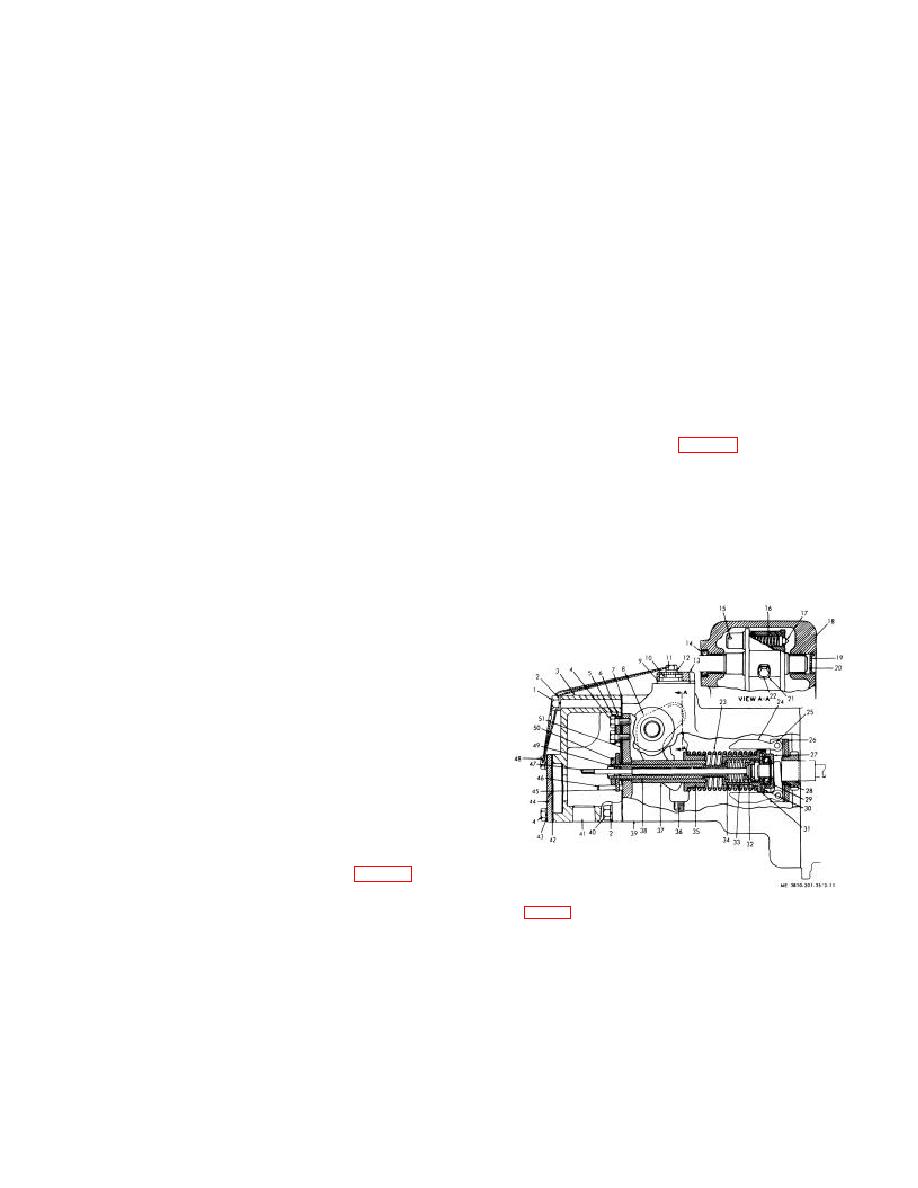
b. Operation. While the engine is operating, the
compression force of governor spring (10, fig. 3-7) is
always pushing to increase engine rpm, and the
centrifugal force of revolving governor weights (7) is
KEY to fig. 3-7:
always trying to decrease engine rpm. Engine rpm is
regulated when the centrifugal force of weights balances
1
Shaft
7
Weights (2 rqr)
2
Stop
8
Trust bearing
the compression force of the governor spring. When
3
Spring
9
Fuel rack
engine load is increased, engine rpm decreases and the
4
Lever
10
Spring
governor weights turn slower thus losing part of their
5
Shoulder
11
Spring seat
centrifugal force. Removal of this force from spring
6
Adapter
12
Bearing
allows spring to move seat (11), connected to fuel rack
(9), to an increased fuel position. With more fuel engine
Figure 3-7. Engine governor, right side cross section
rpm increases, weights (7) swing outward (as weights
view.
3-11


