TM 5-3810-206-35
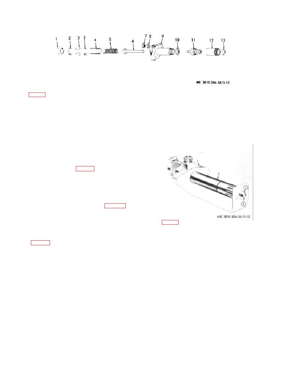
KEY to fig. 3-12:
1
Cap
6
Spindle
11
Fuel injector nozzle
2
Flatwasher (2 rqr)
7
Nut (2 rqr)
12
Nut
3
Nut
8
Lockwasher (2 rqr)
13
Seal
4
Screw
9
Body
5
Spring
10
Gasket
Figure 3-12. Fuel injector, exploded view.
c. Reassembly, Testing, Adjusting, and installation.
(1) Assure that all parts are coated with clean
fuel oil.
(2) Insert spindle (6, fig. 3-12) in body (9).
(3) Install spring (5) and adjusting screw (4) in
body (9).
(4) Install flatwasher (2) and nut (3) in body (9).
(5) Install nozzle (11) and gasket (10) in body
(9) and secure with nut (12).
(6) Install flatwasher (2) and cap (1).
(7) Adjust injector nozzle tip (3, fig. 3-13) at
proper angle by positioning injector (2) in jig (1), then
turning tip until orifice (4) is in alignment with mark 0 on
jig.
KEY to fig. 3-13:
(8) Test fuel injector by installing it on test stand
1 Jig, tip angle setting
3 Nozzle tip
and check for an opening pressure of 2,200 psi.
2 Fuel injector
4 Orifice
(9) When opening pressure is incorrect, remove
cap (1, fig. 3-12), flatwasher (2), and loosen nut (3), then
Figure 3-13. Setting fuel injector nozzle tip angle with
turn adjusting screw (4) clockwise to increase, or
jig.
counterclockwise to decrease pressure.
(10) When pressure tests correctly, tighten nut
(11) Remove injector from test stand.
(3), install flatwasher (2) and can (1).
(12) If fuel injector is to await future installation,
protect against contamination.
(13) Install the fuel injector (TM 5-3810-206-12).
Section VI. BLOWER (SUPERCHARGER) OR TURBOCHARGER
model D333TA. Both serve the same purpose, that of
3-13. General
delivering filtered air under pressure to cylinders for
The blowers (superchargers) are used on engines model
combustion. They will be described in the maintenance
687C-18-ES, and the turbocharger is used on engine
paragraphs that follow.
3-15


