TM 5-3810-207-20/TO 36C23-3-37-12
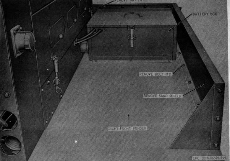
Figure 198. Sand shield removal and installation.
(3)
Inspect the braces for cracks or breaks.
Replace a damaged brace.
(4)
Repair or replace damaged parts as
necessary.
Note.
Minor bends or dents may be
straightened and breaks welded.
c.
Installation.
(1)
Install the right-front fender as illustrated
on figure 201.
(2)
Install the sand shield (par. 320).
(3)
Install the engine hood and side panel
(par. 321).
(4)
Install the battery box (par. 209).
323. Rear Fenders
a.
Removal. Remove the carrier rear fenders as
instructed on figure 202.
b.
Cleaning, Inspection, and Repair.
(1)
Clean all parts with an approved cleaning
solvent.
(2)
Inspect the fender for cracks, breaks, or
bends. Replace a damaged fender.
(3)
Repair or replace damaged parts as
necessary.
c.
Installation. Install the carrier rear fenders as
illustrated on figure 202.
324. Cab and Left-Front Fender
a.
Inspection. Inspect the cab and left-front fender
for breaks, cracks, dents, holes, rust, and broken
braces.
b.
Repair. Weld all cracks, breaks, holes, and
broken braces of the cab and left-front fender. Remove
all dents and refer to TM 92851 for painting a repaired
cab or fender.
258