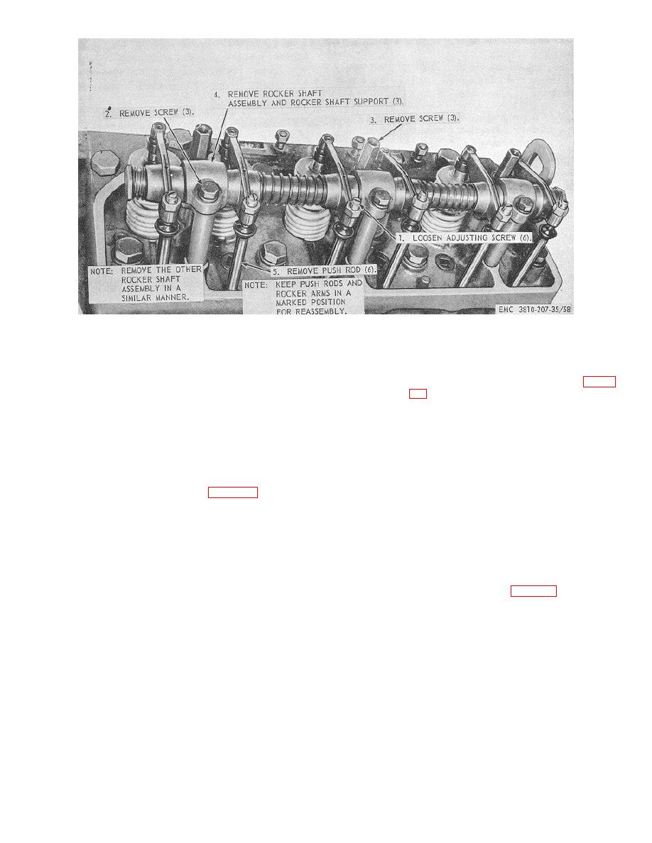
Figure 58. Carrier engine rocker arm shaft and push rods assembly, removal and
installation.
b. Inspection and Repair. Inspect all parts for
b. Installation.
excessive wear, defects, and damage. Replace or repair
(1) Install the carrier engine rocker arm and
all damaged or defective parts. Inspect the rocker arm-
push rods assembly as illustrated on figure
to-shaft clearance. The clearance should measure from
0.0005 to 0.0015 inch.
(2) Install the rocker arm covers (TM 5-3810-
207-20).
(3) Install the spark plug (TM 5-3810-207-20).
241. Carrier Engine Rocker Arm and Push
(4) Install the water manifold (TM 5-3810-207-
Rods Assembly Reassembly and
20).
Installation
a. Reassembly. Reassemble the carrier engine
(TM 5-3810-207-20).
rocker arm and push rods assembly in the reverse of the
numerical sequence as illustrated on figure 59.
Section XI. CARRIER ENGINE CYLINDER HEAD AND VALVES
242. General
243. Carrier Engine Cylinder Head and
The carrier engine cylinder head consists of two
Valves Removal and Disassembly
sections, front and rear. The cylinder head houses the
a. Removal.
exhaust and intake valves. The exhaust valves are
(1) Remove the carrier engine rocker arm and
made of heat resistant steel.
push rods assembly (par. 239).
TAGO 5030A
112


