1
Shaft support screw, 3/8-16 x 4 (6 rqr)
15
Push rod (12 rqr)
2
Washer, lock, 3/8 in. (6 rqr)
16
Valve stem cap (12 rqr)
3
Shaft support screw, special (6 rqr)
17
Valve spring retainer lock (24 rqr)
4
Washer, lock, 3/8 in. (6 rqr)
18
Valve, intake and exhaust (12 rqr)
5
Rocker shaft support (6 rqr)
19
Valve spring upper retainer (12 rqr)
6
Ball socket (12 rqr)
20
Outer valve spring (12 rqr)
7
Spring, long (4 rqr)
21
Inner valve spring (12 rqr)
8
Rocker arm (12 rqr)
22
Valve stem inlet guard (6 rqr)
9
Rocker arm shaft (2 rqr)
23
Valve spring lower retainer (12 rqr)
10
Rocker arm shaft plug (4 rqr)
24
Exhaust valve spacer (6 rqr)
11
Oil plug gasket (4 rqr)
25
Intake valve stem guide (6 rqr)
12
Spring, short (4 rqr)
26
Exhaust valve stem guide (6 rqr)
13
Adjusting screw nut (12 rqr)
27
Push rod tube (12 rqr)
14
Adjusting screw (12 rqr)
28
Dowel, rocker shaft to support (2 rqr)
Figure 59-Continued.
relief valve is equipped to vary the oil pressure to meet
252. Carrier Engine Oil Pump Assembly
the engine requirements.
Cleaning, Inspection, and Repair
a. Cleaning. Clean all parts with an approved
251. Carrier Engine Oil Pump Assembly
cleaning solvent and dry thoroughly.
Removal and Disassembly
b. Inspection and Repair. Inspect all parts for
a. Removal.
excessive wear or damage. Inspect the gears to check
(1) Remove the carrier engine oil pan (par.
for excessive backlash between teeth. There should not
be more than 0.010 inch between teeth. Inspect the
(2) Remove the carrier engine oil pump
clearance between the gear teeth and pump body. The
assembly as instructed on figure 64.
clearance should be between 0.003 and 0.004 inch.
b. Disassembly. Disassemble the carrier engine oil
Replace or repair all defective parts.
pump assembly in numerical sequence as illustrated on
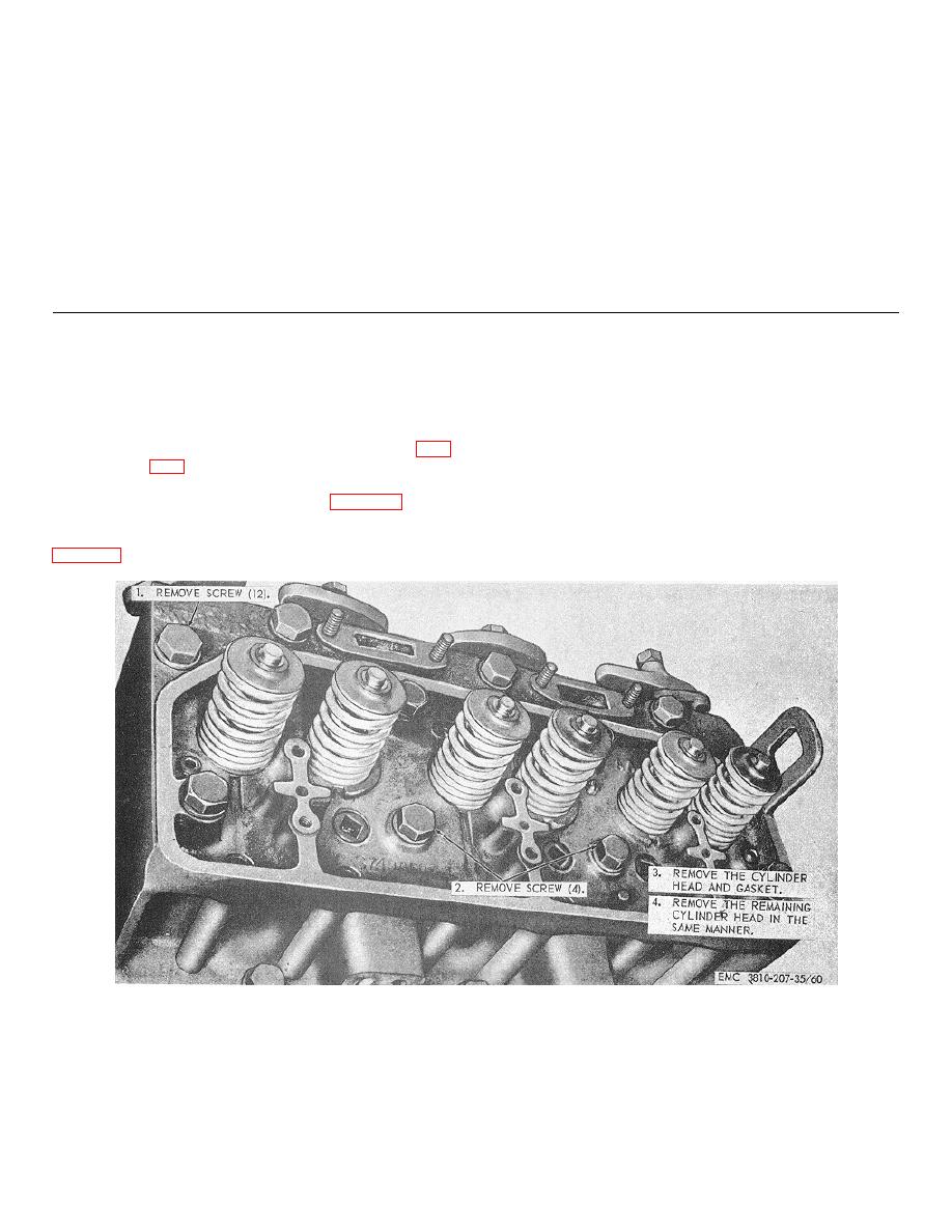
Figure 60. Carrier engine cylinder head and valves, removal and installation
TAGO 5030A
115


