b.
Inspection and Repair. Inspect all parts for
excessive wear or damage. Replace or repair all
defective parts.
353.
Crane
Engine
Oil
Pump
Assem bly
Reassembly and Installation
a.
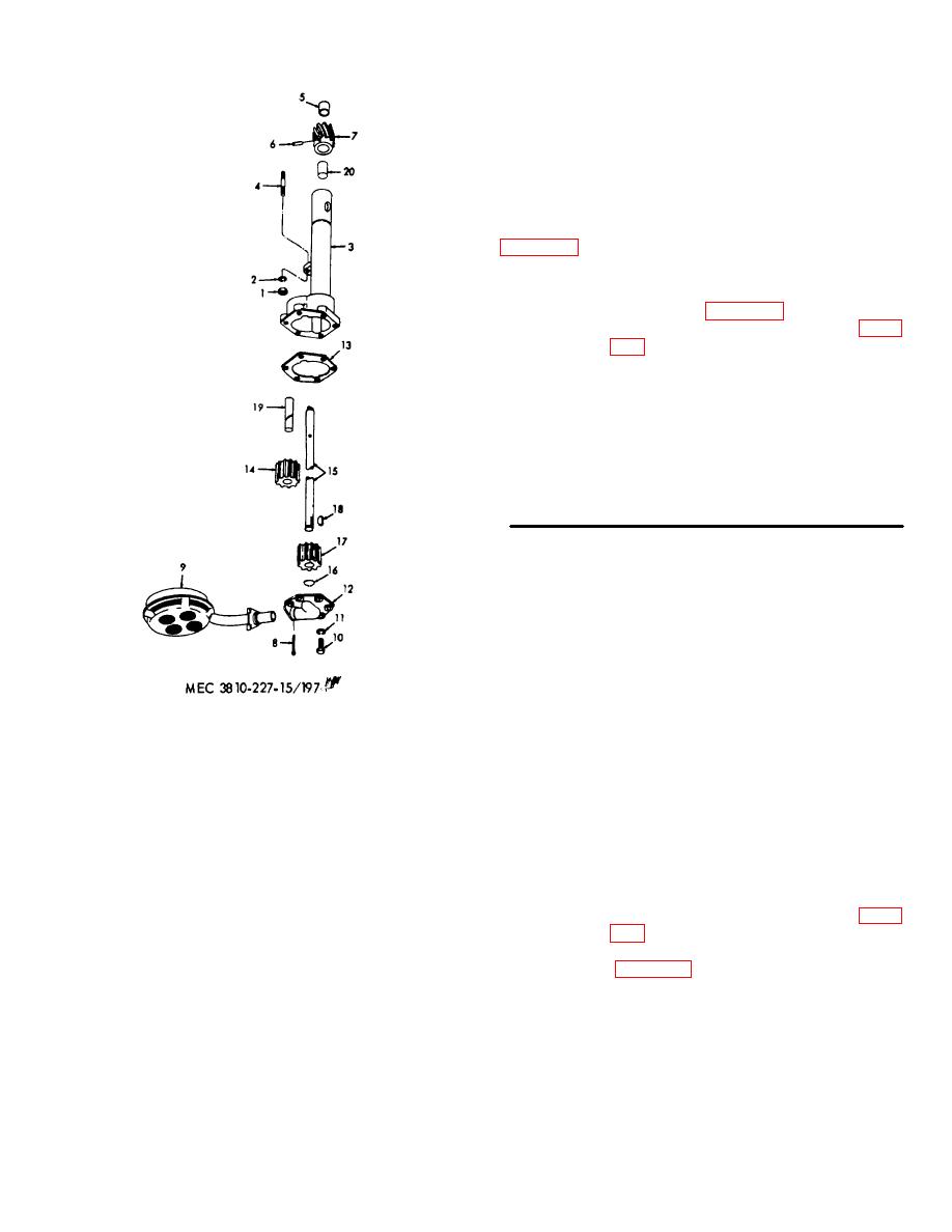
Reassembly. Reassemble the oil pump in
the reverse of the numerical sequence as illustrated on
b.
Installation.
(1) Install the oil pump assembly as
illustrated on figure 196.
(2) Install the crane engine oil pan (para.
1
Nut
11
Washer, lock
2
Washer, lock
12
Cover
3
Body
13
Gasket
4
Stud
14
Idler gear
5
Sleeve
15
Drive shaft
6
Pin
16
Snap ring
7
Helical gear
17
Drive gear
8
Pin, cotter
18
Key
9
Float, screen
19
Shaft
10
Screw, cap
20
Bushing
Figure 197. Crane engine oil pump assembly, exploded view.
Section XVII. CRANE ENGINE PISTON AND CONNECTING ROD ASSEMBLIES
354.
General
355.
Crane Engine Piston and Connecting Rod
Assemblies Removal and Disassembly
The pistons used on the crane engine are
equipped with four rings each; one chrome ring at top of
a.
Removal.
piston, two compression rings, and one oil ring. The
(1) Remove the crane engine oil pan (para.
connecting rods have the insert-type bearing shells.
The bronze piston pin bushing is pressed in the boss of
(2) Remove the crane engine cylinder head
the connecting rod.
AGO 6819A
218


