TM 5-3810-231-12
on each end of trunnions, (A and B, fig.
(2) Adjust operating mechanism as in a
above.
assembly working freely.
b. Removal. Remove operating mechanism as
122. Hydraulic Fluid Reservoir
illustrated on figure 71.
c. Cleaning, Inspection and Repair.
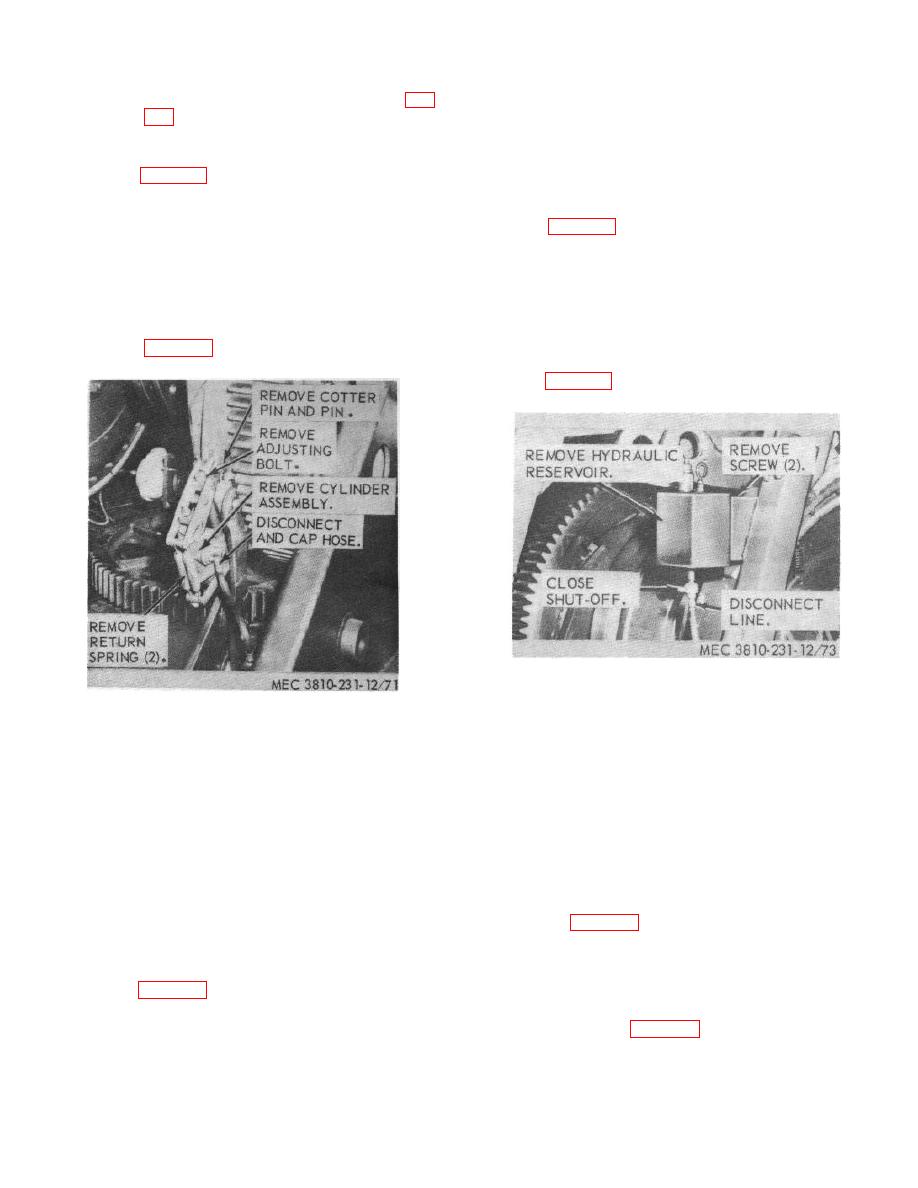
a. Removal. Remove the hydraulic reservoir as
(1) Clean all parts with an approved cleaning
shown on figure 73.
solvent and dry thoroughly.
b. Cleaning, Inspection and Repair.
(2) Inspect for cracks, breaks, and other
(1) Clean and flush with an approved
damage. Repair or replace defective
cleaning solvent and dry thoroughly.
parts.
(2) Inspect for leaks, cracks, breaks or other
d. Installation.
damage. Repair or replace a defective
(1) Install operating mechanism as shown on
reservoir.
c. Installation.
Install the hydraulic reservoir as
shown in figure 73.
Figure 73. Hydraulic fluid reservoir, removal and
installation.
Figure 72. Brake or clutch operating mechanism
assembly.
Section XIX. CRANE AIR SYSTEM
123.
General
(1) Clean gages with a cloth dampened with
an approved cleaning solvent.
(2) Inspect gages for cracked gIass, stripped
The crane air system provides air assist to operating
threads and other damage. Replace a
controls of clutch, brakes, steering and operating
damaged or defective gage.
controls.
c. Installation.
Install the pressure gages as
instructed on figure 74.
124.
Pressure Gages
125.
Pressure Regulating Valve
a. Removal.
Remove the pressure gages as
instructed on figure 74.
a. Removal.
Remove the pressure regulating
b. Cleaning and Inspection.
valve as instructed on figure 74.
101


