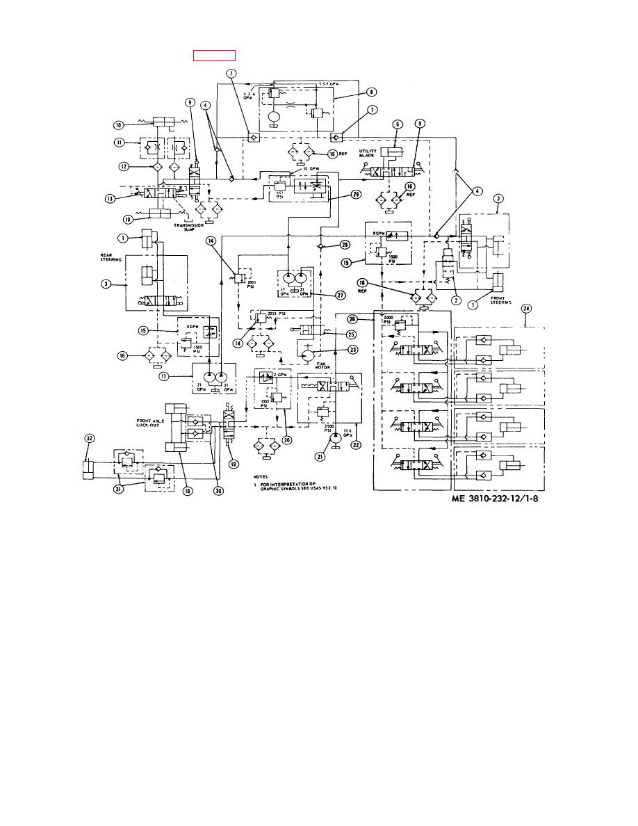
(4) Model 2385 hydraulic diagram (fig. 1-8).
23
Hydraulic fan drive motor
12
Filter, strainer, steering line
1
Cylinder, steering, front
24
Cylinder, outrigger
13
Valve, hand and pilot operated
2
Valve, control front axle
25
Control valve, fan drive
14
Relief valve
3
Cylinder, steering rear
26
Directional control valve
15
Flow control and relief valve
4
Check valve
27
Dual hydraulic pump, utility blade
16
Oil filter, hydraulic
5
Control valve, utility blade
and fan drive motor
17
Dual hydraulic pump, front and
6
Cylinder, utility blade
28
Check valve, right angle
rear steering
7
Check valve
29
Flow divider valve
18
Lockout cylinder, front axle
8
Hydraulic
pump,
emergency
30
Double check valve
oscillate
steering
31
Relief and check valve
19
Double solenoid valve
9 Control valve, steering
32
Cylinder,
lockout-trans.
Gear
20
Flow control and relief valve
10 Cylinder, centering, front and rear
range selector
21
Hydraulic pump, outrigger and
axle
front axle oscillate lockout
11 Check valve
Figure 1-8. Hydraulic diagram (model 2385).
1-15


