c. Cleaning, Inspection and Repair.
socket and an inch pound torque wrench check the inch
pounds required to pull the input shaft through the center
(1) Clean all parts with an approved cleaning
position. Acceptable torque is 11 to 15 inch pounds.
solvent and dry thoroughly.
(c) If input shaft pull is not within
(2) Inspect all parts for cracks, breaks and
specified limits, loosen lock nut and turn lash in order to
other damage. Repair or replace defective parts.
bring torque pull of the input shaft within limits. Always
d. Reassembly.
Refer to figure 5-13
and
recheck pull valve after lock nut has been tightened.
reassemble the steering gear boxes as illustrated.
(d) Loosen lock nut on back-up adjuster
e. Installation. Refer to figure 5-13 and install the
steering gear box.
1/8 to 1/4 turn and tighten lock nut.
5-14. Carrier Steering Gear and Valve Assembly
(e) After all adjustments have been
a. Steering Gear Adjustments.
made install the steering box in the vehicle frame. Install
the pitman arm on the sector shaft aligning with the
(1) General. The steering gear assembly is
reference marks established at time of disassembly.
designed to provide adjustment to compensate for
normal wear at worn bearings, pitman shaft, and mating
parts. The starting gear box discussed here is
mounted on the frame.
(2) Steering gear box removal.
(a) Disconnect drag link from pitman
arm. Note relative position of linkage and pitman arm so
parts may be reassembled in the same relative position
(b) Adjust worn bearings as follows:
Proper adjustment of worn bearings is obtained by
adding or removing shims between steering gear
housing and top cover or end cover (fig. 5-14). Shims
are available in thickness of 0.002", 0.005", and 0.030".
Refill gear housing with lubricant (refer to lubrication
order).
(c) Assemble steering gear box in
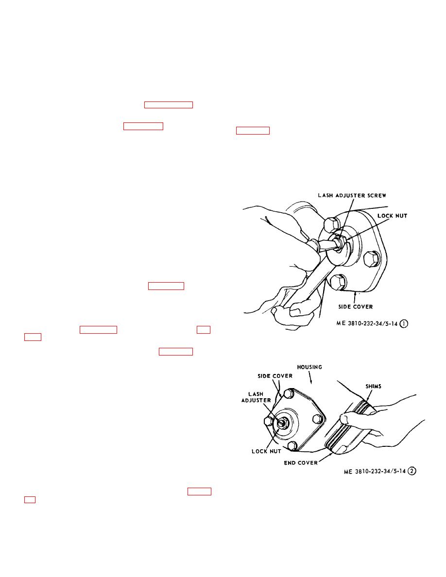
accordance with figure 5-14. With the lock nut loose (fig.
A-Sector gear lash adjustment (Model 2385)
to relieve the load from the worm bearing and to provide
Figure 5-14. (1) Steering gear and valve adjustment
clearance between the sector gear (16, fig. 5-14) and
(Model 2385).
the worn ball nut (28). Turn the worm shaft (27) by hand,
in one direction until it stops, then back off one full turn.
Using a 12 point socket wrench and an inch pound
torque wrench, check the torque required to move the
shaft and keep it moving. Correct torque is 5 to 9 inch
pounds. If torque is not within tolerance, add or remove
shims as required.
(3) Pitman shaft lash adjustment,
(a) Center the steering gear by turning
the input shaft from extreme left positions, counting the
exact number of turns and factions thereof. Turn the
input shaft back exactly halfway to center position. Mark
the input shaft and the housing so as to establish a
center position reference point.
B-Installing and cover shims (Model 2385)
(b) Loosen lash adjuster lock nut (fig. 4-
Figure 5-14. --Continued.
backlash between gear teeth. Tighten 5-32 adjuster
screw lock nut 25 to 35 ft-lbs. torque. Using a 12 point
5-32


