TM 5-3810-288-12
lever as far in that direction as it can go. In Sketch 3, the
operator has pushed the control lever past the toggle
point. The lever will now stay in the forward position until
the operator pulls it back, past the toggle point, to the
neutral (centered) position. It is most important that only
the four levers which are designed for toggle linkage
action, and which are listed above be allowed to "toggle
in". Refer to figure 3-16 and adjust toggle linkage.
3-27. Shovel Front Attachment
a. Service. The shovel front must be lubricated at
the periodic intervals listed in the lubrication order.
When removed from the machine, all exposed finished
surfaces must also be lubricated as often as required to
prevent damage due to rust and corrosion. If possible,
the entire attachment should be placed inside a suitable
dry building, preferably on wooden blocking. The shovel
front should be cleaned using an approved cleaning
solution.
b. Adjust. Each of the following adjustments must
be checked every 40 hours of shovel operation. Adjust
only if necessary.
(1) Saddle block adjustment. Shims and wear
plates are used to adjust the clearance between the
dipper stick and the saddle block wear plates as shown
in figure 3-17.
The desired minimum clearances
between wear plates and saddle blocks are 1/64 inch at
each location. Adjustment is mandatory when clearance
reaches 1/16 inch at any point illustrated. Use the
following procedure for adjustment.
(a) Support the dipper stick in a horizontal
position, using the hoist line.
(b) Divide the dipper stick into three
approximately equal lengths, using chalk marks or paint.
(c) Move the dipper stick back and forth a few
times to make sure it is free in the saddle blocks and in
it's normal operating condition.
(d) Position the dipper stick so that the outer third
of the dipper stick, as measured by the chalk or paint
marks, is located in the saddle block. Measure the
clearance between the wear plates on each side of the
dipper stick and the dipper stick. Record the clearance
measured.
(e) Measure the clearance between the top of the
dipper stick and the wear plate at each
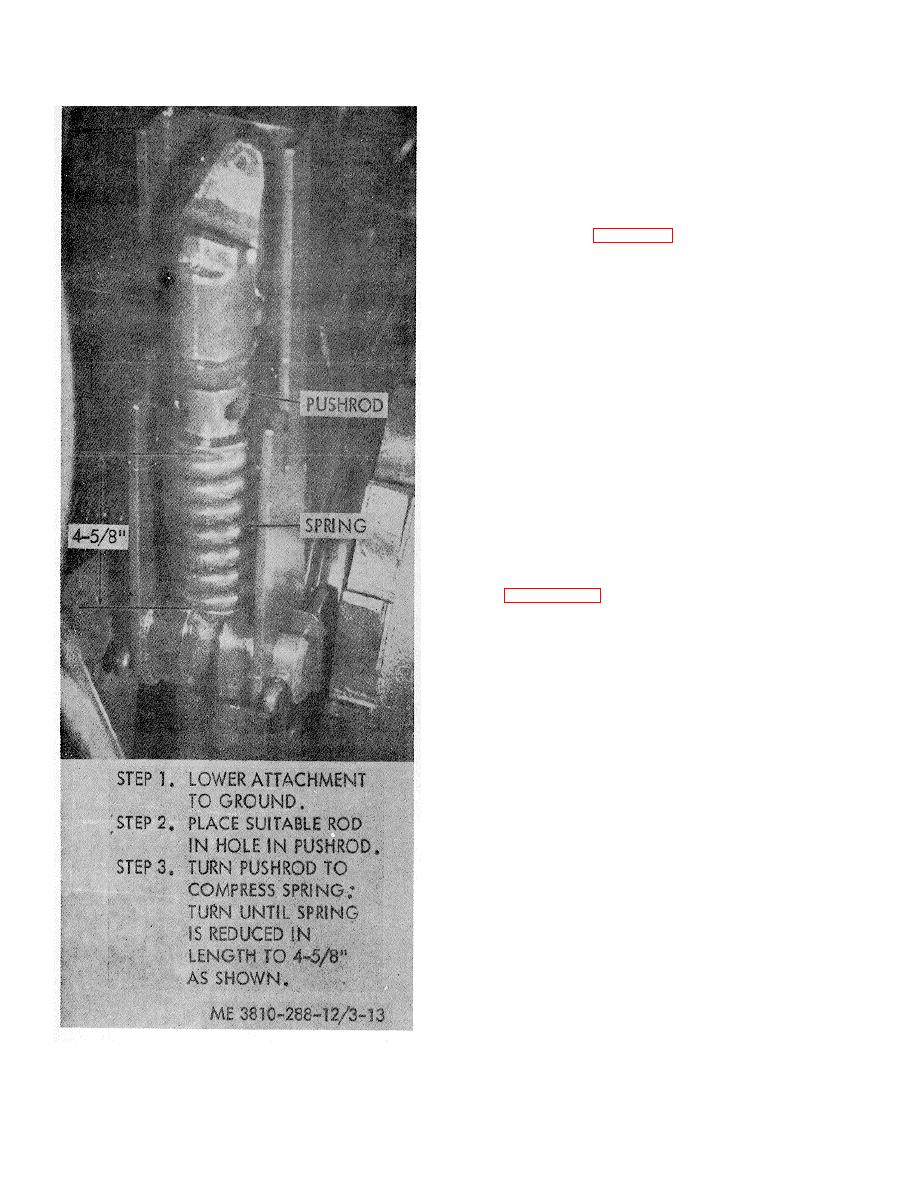
Figure 3-13. Adjusting boom hoist brake.
3-15
.


