TM 5-3810-288-12
1. Nut
14.
Knob, air brake
27.
2. Bracket
15.
Plate instruction
28.
Plate, name
3. Bracket
16.
Knob, differential lockout
29.
Screw, drive
4. Nut
17.
Plate, instruction
30.
Switch, cab heater
5. Plate
18.
Knob, windshield wiper
31.
Receptacle, ignition
6. Plate, name
19.
Setscrew
32.
Lamp
7. Gauge
20.
Tachometer-hourmeter
33.
Switch, hazard warning
8. Lamp
21.
Speedometer-odometer
34.
Switch lamp selector
9. Pump
22.
Gauge, carrier fuel
35.
Plate, speed chart
10. Knob, throttle
23.
Switch, panel lamp
36.
Screw
11. Plate, name
24.
Lamp
37.
Switch, toggle
12. Knob, air brake
25.
Gauge, oil pressure
13. Pin
26.
Gauge, water temperature
Figure 7-20. Instrument panel switch, and gage, removal and replacement
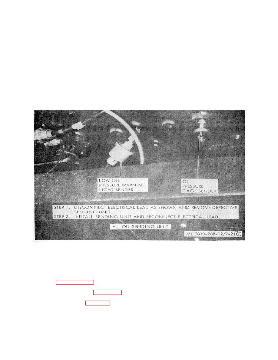
Figure 7-21. Sending units, removal and replacement. (Sheet 1 of 2)
and remove and replace a defective fuel tank sending
(2) Wiring harness repair. The method of
unit.
repairing the instrument panel wiring harness is the
l. Trailer Coupling and Chassis Wiring.
same as the method used in repairing any other wiring
(1) Trailer coupling replacement. There
harness. Refer to paragraph 3-49k and repair the
are two trailer couplings on the machine. One is
instrument panel wiring harness.
mounted on the rear of the carrier frame and the other is
k. Sending units. Refer to figure 7-21 and
mounted on the rear of the outrigger box. The method of
remove and replace a defective oil pressure or water
removing both of the trailer
temperature sending unit. Refer to figure 7-13
7-25


