TM 5-3810-288-12
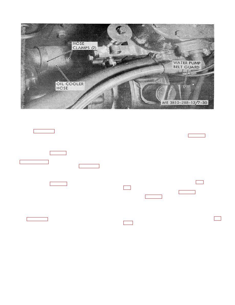
Figure 7-30. Water pump and lines, removal and replacement.
replacement.
(e) Refer to figure 7-32 and loosen the fan hub bracket
(4) Belt tension adjustment. Leave the fan hub
mounting bolts. Loosen the jam nut on the fan belt
bracket mounting bolts loose (fig. 7-34).
adjusting bolt and back off on the adjusting bolt until
Loosen the jam nut and tighten the fan belt ad-
the belts are slack enough for removal. Remove the
justing bolt until the fan belts have a maximum of
belts.
about I/ inch midspan slack at the longest span.
(f) If the fan sheave (fig. 7-34) is to be removed, it will
Tighten the fan hub bracket mounting bolts so
be necessary to remove the radiator as instructed in
that the correct belt tension will be maintained.
Tighten the jam nut.
(g) With the radiator removed, refer to figure 7-32 and
continue with the removal of the fan sheave
7-44. Power Steering System
components. Note that items 9 through 14 have
already been removed.
a. General. The power steering system (fig.
(h) Remove nut (15, fig. 7-32). Remove items (16
through 22), as an assembly, using a suitable puller
which contains a fluid reservoir (fig. 7-35), the steering
bearing against the end of shaft (24) and screwed
gear proper (fig. 7-33), which contains a hydraulic
into the tapped holes in sheave (20). Remove all
control valve and a power cylinder, and a mechanical
items mounted in sheave (20) by removing retaining
means of steering control. The operator is able to steer
ring (22). Then press out items (16 through 21).
the machine even if hydraulic power is lost, although
(3) Installation. Install the components of the fan,
additional effort will be required. Mechanical power from
fan sheave, and associated parts as shown in
the steering gear is transmitted through the drag link (fig.
installed, lubricate in accordance with the
lubrication order and adjust belt tension as
follows.
b. Power Steering Pump and Reservoir.
(1) Removal. Remove the power steering pump and
reservoir and the pump drive belt as follows:
7-37


