TM 5-3810-289-34
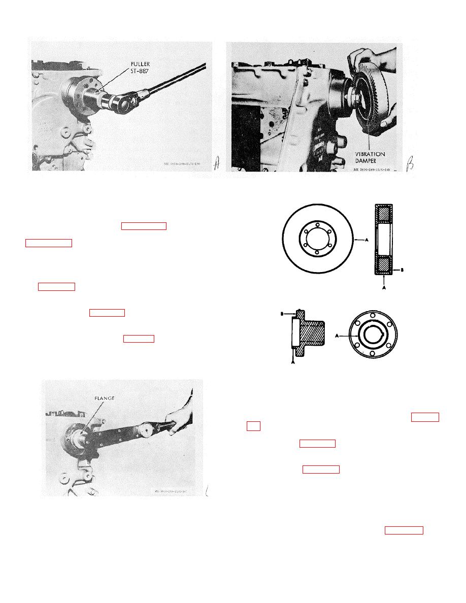
Figure 3-178. Crankshaft hub removal.
Figure 3-180. Vibration damper installation.
e. Installation.
(1) Slide flange over crankshaft end; secure
with large retainer washer and Nylon capscrew. Torque
capscrew to 120/140 ft.-lbs., figure 3-179.
(2) Place vibration damper over flange,
(3) Torque capscrews to 85/45 ft.-lbs.
(4)
Eccentricity of vibration damper
mounting fange measured on the outside diameter of the
pilot must not exceed 0.004 in. total indicator reading,
(A, fig. 3-181).
(5)
Wobble in the vibration damper
mounting flange must not exceed 0.003 in. measured at
23/4 in. radius (B, fig. 3-181).
(6)
After assembly, vibration damper
maximum allowable runout (total indicator reading) must
not exceed values shown in table 2-2.
Note. Make checks with dial indicator measured
on smooth inner ledge of inertia member.
Keep
crankshaft thrust clearance to front or rear limit while
Figure 3-181. Vibration and crankshaft hub eccentricity
checking wobble.
and wobble measurements.
3-39. Gear Cover
a. General.
(1) Remove accessory drive pulley (para 3-
(2)
Remove vibration damper and
crankshaft hub (para 3-38).
(3) Remove all capscrews and lockwashers
securing cover to block (including two capscrews behind
mounting plate) (fig. 3-182).
(4) Lift gear cover from engine.
(5) Remove and discard gasket.
b. Inspection.
Figure 3-179. Crankshaft hub installation.
(1) Inspect gear cover for cracks or other
defects.
(2) Remove all oil seal and bearings. (8)
Inspect gear trunnion outside diameter (fig. 3-183) for
wear. If excessive, install a bushing as described in
subparagraph c.
3-64


