DETROIT DIESEL 53
Main Bearings 1.3.4
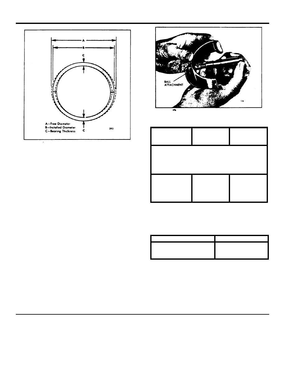
Fig. 7. Measuring Thickness of Main Bearing
Shell
Nominal
Minimum New
Crankshaft
Size of
Bearing Shell
Main Bearing
Bearing
Thickness
Journal Dia.
Fig. 6 - Inside Diameter of Main Bearing Shell at
Parting Line and 90 Degrees to Parting Line
V-Type Engines
Standard
.1240"
3.499"-3.500"
The upper and lower main bearing shells are not alike;
.002" Undersize
.1250"
3.497"-3.498"
the upper shell is grooved and drilled for lubrication -the
.010" Undersize
.1290"
*3.489"-3.490"
lower shell is not. Be sure to install the grooved and
.020" Undersize
.1340"
*3.479"-3.480"
drilled shells in the cylinder block and the plain shells in
.030" Undersize
.1390"
*3.469"-3.470"
the bearing caps, otherwise the oil flow to the upper end
of the connecting rods will be blocked off. Used bearing
Table 1
shells must be reinstalled on the same journal from
which they were removed.
1. When installing the upper main bearing shells
with the crankshaft in place, start the plain end of the
Nominal Size
Washer Thickness
shell around the crankshaft journal so that, when the
Standard
.1190"/.1220"
shell is in place, the tang will fit into the groove in the
.005" Oversize
.1255"/.1270"
bearing support.
.010" Oversize
.1300"/.1320"
2. Assemble the crankshaft thrust washers before
installing the main bearing cap. Clean both halves of
TABLE 2
the thrust washer carefully and remove any burrs from
the washer seats -the slightest particle of dirt may
NOTE: The main bearing caps are
decrease the clearance between the washers and the
bored in position and marked 1, 2,4, etc.
crankshaft beyond limits. Slide the upper halves of he
They must be replaced in their original
thrust washers into place in their grooves (Fig.8), then
positions with the marked side of the
assemble the lower halves over the dowel pins in the
caps facing the same side of
bearing cap.
1972 General Motors Corp.
February, 1972
SEC. 1.3.4 Page 5


