DETROIT DIESEL 53
Piston and Piston Rings
1.6
clockwise direction only, when reaming or withdrawing
Fitting Piston Rings
the reamer. For the best results, use only moderate
pressure on the reamef.
Use new piston rings whenever a piston is removed for
inspection or replacement.
5. Withdraw the reamer and remove the piston from the
fixture. Blow out the chips and check the inside
The
top compression (fire) ring can be
diameter of the bushings. The inside diameter of the
identified by the bright chrome on the bottom side and
bushings must be 1.3775" to 1.3780".
oxide (rust color) on the top.
Fitting Piston
Insert one piston ring at a time far enough down in the
cylinder liner to be within the normal area of ring travel.
Use a piston to push the ring down to be sure it is
Piston and cylinder liner measurements should be taken
parallel with the top of the liner. Then measure the ring
at room temperature (70F.).
gap with a feeler gage as shown in Fig. 9. Refer to
Section 1.0 for the specified ring gap.
Measure the piston skirt diameter in the area between
the bottom of the oil compression ring grooves and the
If the piston ring gap is below the specified limits, it may
top of the oil control ring grooves, except near the piston
be increased by filing or stoning the piston ring in such a
pin bore.
direction that the file or stone will cut from the outside
(chrome plated) surface of the ring toward the inside
The diameter of a new piston is 3.8699" to 3.8721'. The
surface. This will prevent any chipping or peeling of the
inside diameter of a new cylinder liner is 3.8752" to
chrome plate. The ends of the ring must remain square
3.8767". Therefore, with new parts, the piston to liner
and the chamfer must be approximately .015" on the
clearance .0031" to .0068" and should not exceed .010"
outer edge.
with used parts.
Check the ring clearances in the piston grooves as
After inspecting and installing the cylinder liner (new or
used) as outlined in Section 1.6.3, check the piston-to-
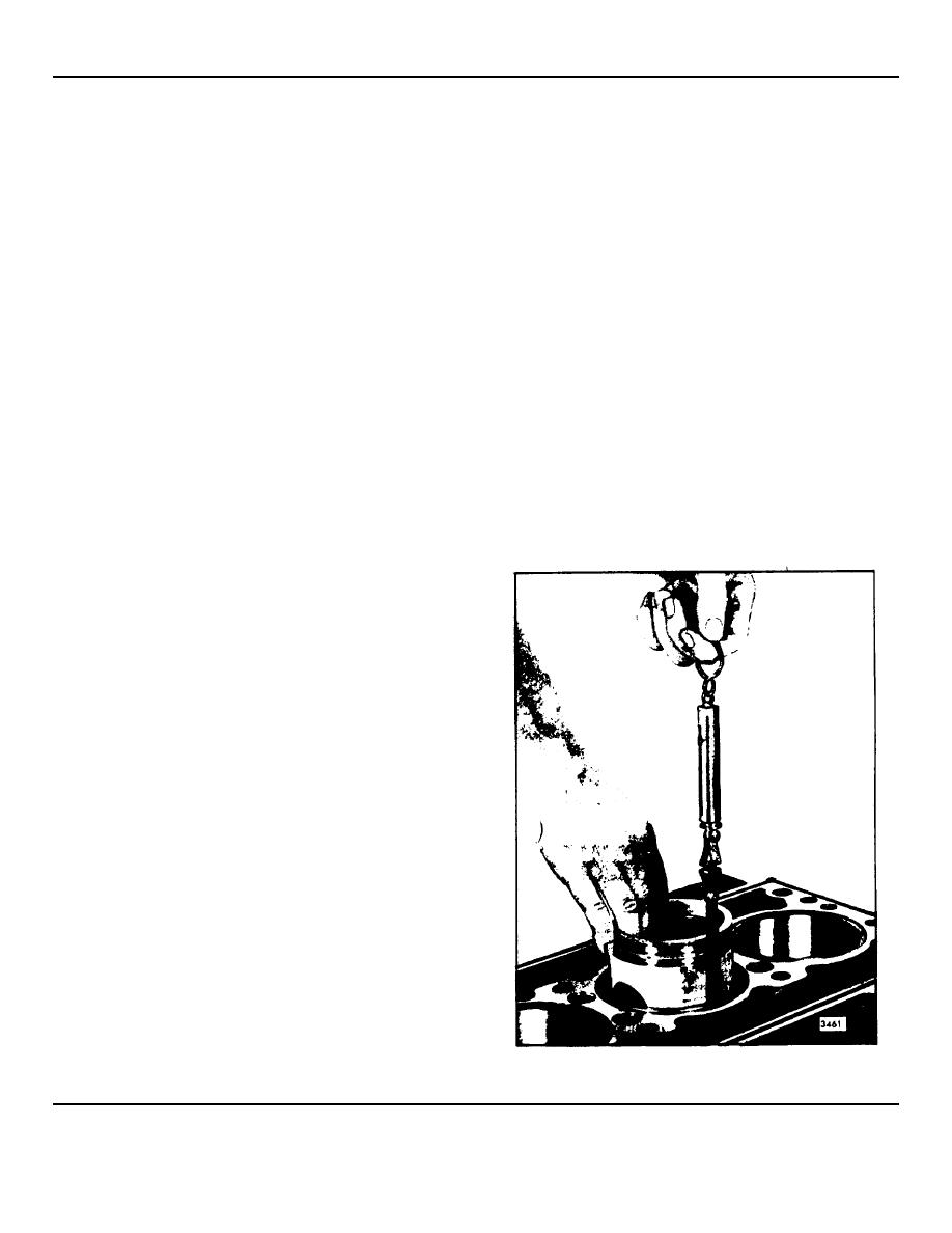
liner clearance. Check this clearance in four places, 90
apart, while holding the piston upside down in the
cylinder liner (Fig. 8).
Feeler gage set J 5438 may be used for checking the
piston-to-liner clearance. The spring scale, attached to
the appropriate feeler gage, is used to measure the
force in pounds required to withdraw the feeler gage
from between the piston and liner.
The clearance will be .001" greater than the thickness of
the feeler gage used, i.e., a .004" thick feeler gage will
indicate a clearance of .005" when it is withdrawn at a
pull of six pounds. The feeler gage must be perfectly
flat and free of nicks and bends.
If any bind between the piston and liner is detected,
remove the piston and inspect the piston and liner for
burrs. Remove the burrs with a fine hone (a flat one is
preferable) before proceeding with the clearance check.
Fig. 8. Measuring Piston-to-Liner Clearance
1972 General Motors Corp.
February, 1972
SEC. 1.6 Page 5


