DETROIT DIESEL 53
Blower 3.4
shafts with the missing serrations in alignment with the
missing serrations on the shafts.
8 Tap the gears lightly with a soft hammer to seat t em
on the shafts. Then rotate the gears until the punch
marks on the face of the gears match. If the marks do
not match, re-position the gears.
9. Wedge a clean cloth between the blower rotor;. Use
the gear retaining bolts and plain washers to prep, the
gears on the rotor shafts (Fig.8.) Turn the bolts
uniformly until the gears are tight against the shoulders
on the shafts.
10. Remove the gear retaining bolts and washers.
Then proceed as follows:
6V Blower-Place a pilot in the
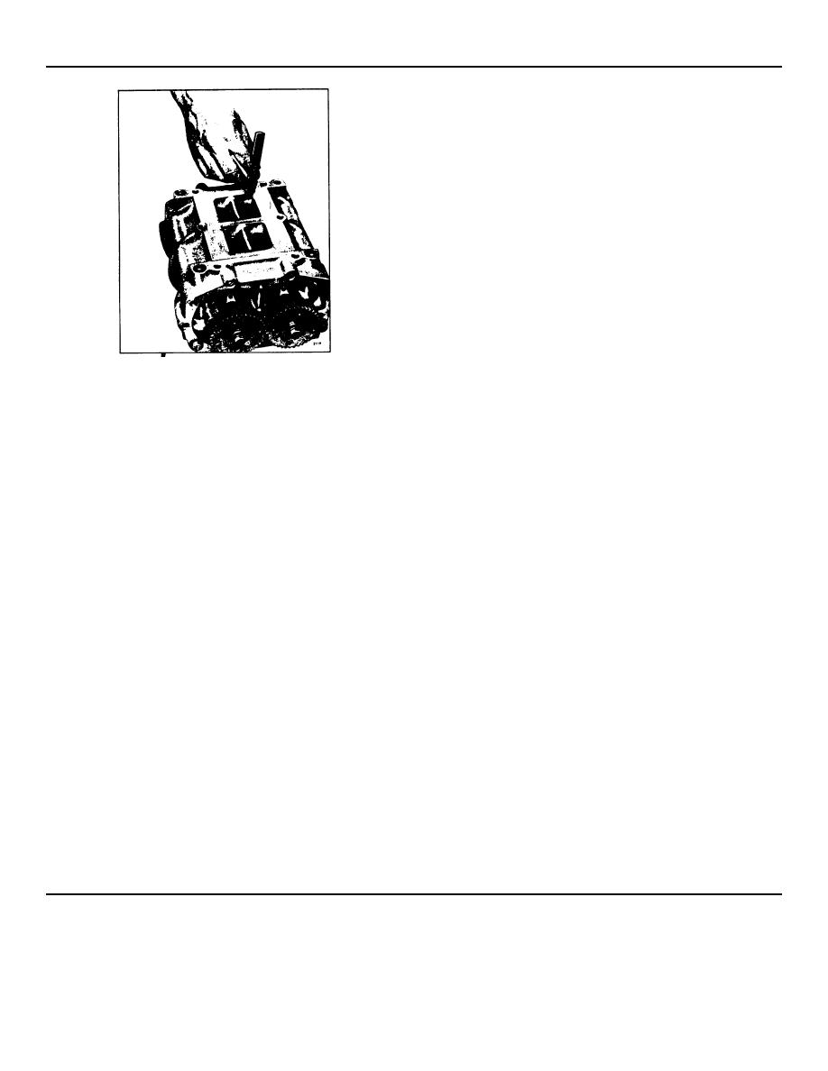
Fig. 11. - Measuring Rotor Lobe to End Plate Clearance
counterbore each gear and start the 12-
point bolt in the right hand rotor shaft and
Secure each end plate to the 6V blower with four end
start the hex head bolt in the left-hand
plate cover bolts and plain washers.
rotor shaft. Tighten the bolts to 25-30 Ib-ft
torque.
5. Attach the two thrust washers to the front end of the
blower with the washer retaining bolts. Tighten them to
11 Check the backlash between the blower gears, using
54-59 lb.-ft torque.
a suitable dial indicator. The specified backlash is .0005
" to .0025 " with new gears or a maximum) .0035 " with
6. Attach the three spacers and the thrust plate to the
used gears.
front end of the blower. Tighten the three bolts to 7-9
lb.-ft torque. Then check the clearance between the
12. Time Blower Rotors
thrust plate and the thrust washers. The specified
clearance is .001 " to .003 ".
After the blower rotors and gears have been installed,
the blower rotors must be timed. When properly
7. Position the rotors so that the missing serrations on
positioned, the blower rotors run with a slight clearance
the gear end of the rotor shafts are 90 apart. This is
between the rotor lobes and with a slight clearance
accomplished by placing the rotors in a "T" shape, with
between the lobes and the walls of the housing.
the missing serration in the upper rotor facing to the left
and the missing serration in the lower rotor facing
The clearances between the rotors may be establish :d
toward the bott6m (Fig. 4.). Install the shims and
by moving one of the helical gears out or in on the shaft
spacers in the counterbore in the rear face of the rotor
relative to the other gear by adding or removing shims
gears. Then place the gears on the ends of the
between the gear hub and the rotor spacers.
It is preferable to measure the clearances with a feels r
gage comprised of two or more feelers, since a
combination is more flexible than a single feeler gage.
Take measurements from both the inlet and outlet sides
of the blower.
a.
Measure the clearance between the rotor
lobes
and
1972 General Motors Corp.
July, 1972
SEC. 3.4 Page 9


