
AIR SYSTEM COMPONENTS
SUB-SECTION 9C
REMOVAL. To remove the throttle selector valve, proceed
3. Reconnect the air lines to the valve.
as follows:
4. Check the operation of the valve by performing the
1. Drain the air system by opening the drain cocks on each
Leakage Test.
reservoir.
2. Disconnect the air lines at the valve.
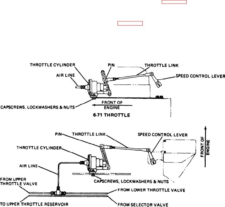
THROTTLE CYLINDER (36U30)
3. Remove the two screws on the valve dial, and remove
DESCRIPTION. The throttle cylinder is a single acting,
the valve dial. The valve can now be removed from the cab
spring returned, air cylinder. This air cylinder is connected
wall.
to the engine speed control lever, and is used to control the
speed of the engine (see Figure 9C-13).
INSTALLATION. To install a new throttle selector valve,
proceed as follows:
When air is applied to the control port of the cylinder, the
piston is forced outward against the return spring (see
1. Place the valve on the engine side of the cab wall with
Figure 9C-14). The amount of piston travel is proportional
the screw holes properly aligned with the holes in the cab
to the amount of air delivered to the cylinder by the
wall.
throttle valve. Therefore, the piston will move further out-
ward when more air is applied to the cylinder and will be
2. Place the valve dial over the valve. Then install the
moved inward, by the return spring, when the applied air
pressure is reduced.
screws to secure the valve to the cab wall.
6V53 THROTTLE
Figure 9C-13. Throttle Arrangements
9C-14