TM 5-3810-295-34
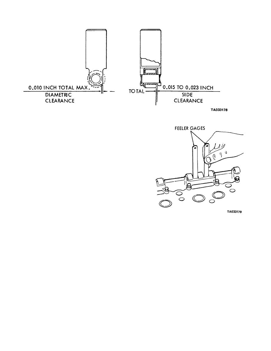
Figure 4-5. Cam roller clearancre specifications.
i
Install lower spring seats (27) on each push rod
(28). Place push rod springs (26).
j
Install spring seat retainers (24) in the cylinder
head. Slide the push rod, spring, and seat assemblies
into the cam follower bores from the bottom of the
cylinder head.
k Screw the push rod lock nuts (23) down on the up-
per end of the push rods as far as possible. Then screw
the push rods into clevis (32) until the end of the rod is
flush with or above the inner side of the clevis.
l
Immerse the cam follower assemblies (53) in clean
engine oil heated to 100 to 125F. for at least one hour.
This will insure lubrication between the cam follower
roller pins and the roller bushings. Rotate the cam
follower roller during the soaking period to purge any
air from the bushing-roller area.
m Note the oil hole in the bottom of the cam
follower. With this oil hole pointing away from the ex-
haust valves, slide the cam follower assembly (53) into
position from the bottom of the head.
n Attach the cam follower guides (51) to the bottom
of the cylinder head. Secure the guides with screws (49)
and lock washers (50). Tighten screws (49) to 12-15 ft-
lb (16-20 N. m). Check to be sure there is at least
Figure 4-6. Checking clearances between cam followers and
0.005-inch clearance between the cam follower and the
cam follower guides.
cam follower guide. (Refer to fig. 4-6.) If there is not
enough clearance, loosen the screws slightly and tap
each corner of the guide with a bras rod. Retighten the
screws and recheck the clearance.
o Install exhaust manifold studs (67). Install pipe
plug (61) expansion plug (62), plug (63), 64), (65) and
(66). Install new gasket (60) and cover (59 Secure
4-6


