TM 5-3810-295-34
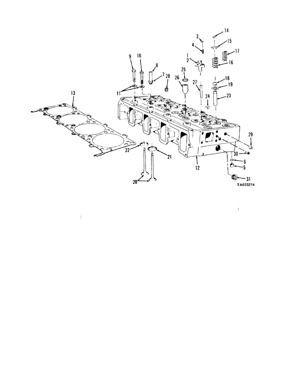
1 Intake crosshead
12 Cylinder head
22 Insert
2 Exhaust crosshead
13 Gasket
23 Guide
3 Crosshead nut
14 Lock
24 Ring
4 Adjusting screw
15 Guide
25 Preformed packing
5 Dowel
16 Outer spring
26 Sleeve
6 Preformed packing
17 Inner spring
27 Guide
7 Nut
18 Seal
28 Plug
8 Tube connector
19 Wear plate
29 Plug
9 Headbolt
20 Valve
30 Plug
10 Headbolt
21 Insert
31 Plug
11 Washer
Figure 14-18. Cylinder head-exploded view.
b. Crosshead guides (27), injector sleeves (26),
(18) over stems until properly seated on valve guides.
packing (25), rings (24) valve guides (23), exhaust
Remove plastic sleeves.
inserts (22), and intake inserts (21) shall have been
f. Assemble springs (17) and springs (16). Up to
1/26-inch spacers may be used to reduce valve spring
installed as described in paragraph 14-19.
length if cylinder head has been reground.
c. Lubricate stems of valves (20) with clean engine
oil and insert valves (20) in valve guides (23). Tem-
CAUTION
porarily hold valves in place with a strip of masking
Using an excessive amount of spacers will
tape.
cause the compress spring to become a solid
NOTE
sleeve.
G Assemble upper valve guide (15). Compress
Valve must be installed in same inserts to
valve springs using a suitable compressor. Install new
which they were checked.
locks (14).
d. Place cylinder head face down on wooden bench
or blocks to protect the milled surface.
14-21. Installation
e. Install wear plates (19) over valve guides. Place
Refer to figure 14-18.
plastic sleeve over valve stems and press seals
a. Clean mating surfaces of cylinder block and
14-18


