TM 5-3810-295-34
b. Disassemble cylinder head as described below.
All carbon must be removed from the intake manifold
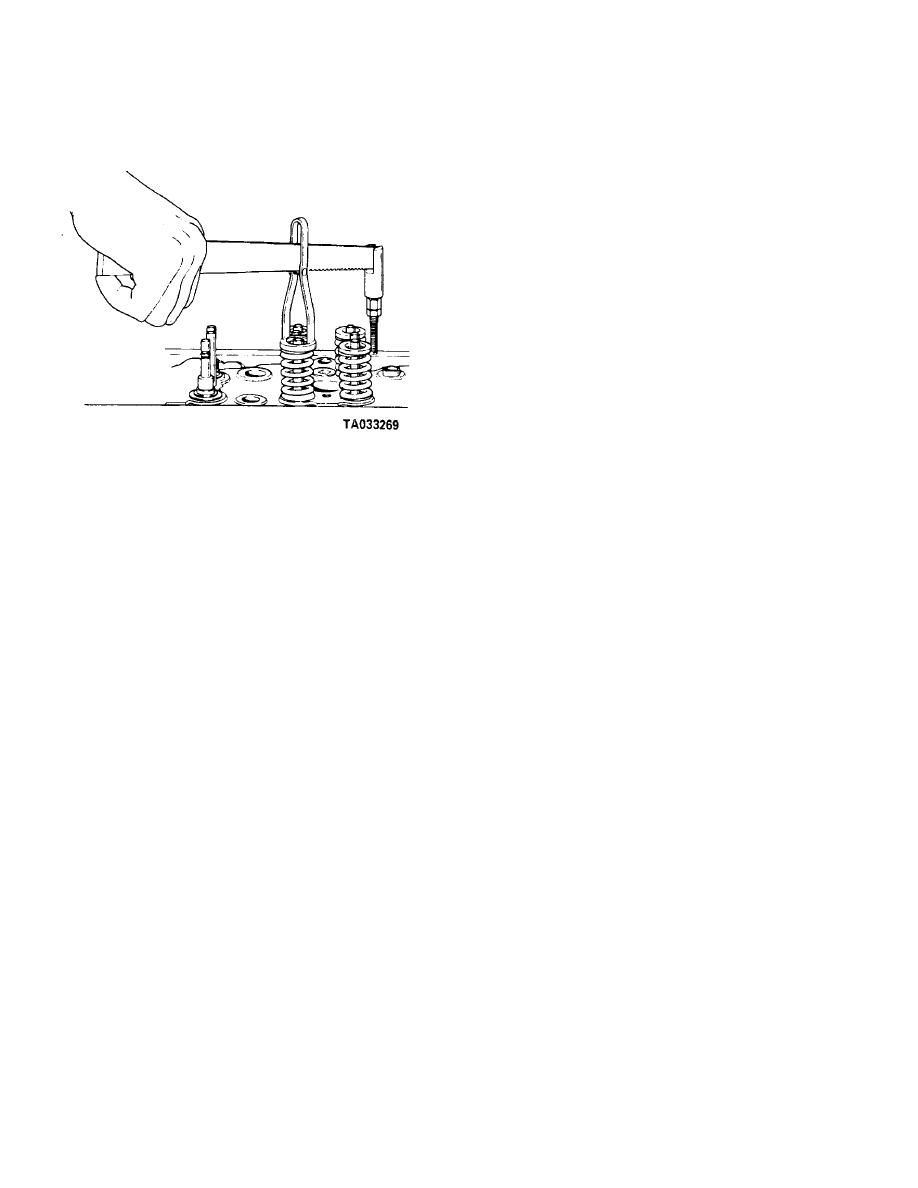
(1) With a suitable valve spring compressor,
section, bottom face of the head, and from the valve
figure 14-13, compress valve springs and remove locks
ports and guide bores.
(14, fig. 14-12).
c. Flush out water passages to remove any ac-
cumulation of salt, slime, or sludge.
d. Clean fuel passages with a long handled brush.
Flush passages with cleaning solvent to remove
deposits.
14-18. Inspection and Repair
a. Inspect heads for water leaks or cracks in the
combustion chamber, exhaust ports, or around the
valve seats. Check the cylinder head for leaks as
follows:
(1) Install an injector sleeve holding tool or a
scrap injector assembly in each injector sleeve. Tighten
hold-down screws to 10-12 ft-lb (14-16 N ‡ m) torque
to seal lower end of injector sleeve.
(2) Seal off the water holes in head with steel
plates and suitable rubber gaskets held in place with
bolts.
(3) Drill and tap into one of the temporary water
Figure 14-13. Valve spring compressor, typical
hole plates for an air hose connection. Apply 30 to 40
psi air pressure with head completely submerged in
(2) Release valve springs and remove guides
water heated to 180-200F. Over a period of 20
(15), outer springs (16), inner springs (17), valve seals
minutes observe for air bubbles which would indicate
(18), and wear plates (19).
leaks or cracks in the head.
CAUTION
(4) Replace head if cracks are evident.
When valve springs are removed on an assem-
Replace any leaking injector sleeves.
bled engine, piston must be up to support
b. Check water passage running full length of head
valves in cylinder. Springs must be replaced
between valves for restriction. If plugged, open by rod-
before barring the engine or valve will drop
ding or drilling.
into cylinder necessitating cylinder head re-
c. Check lubricator oil restrictor plug and lubricat-
moval.
ing passages.
(3) Remove valves (20). If necessary per
d. Inspect fuse plug for signs of overheating. If
paragraph 14-18 remove intake inserts (21), exhaust
fuse plug has melted, check carefully for further damage
inserts (22), and valve guides (23). Identify valves as to
to head and engine.
location.
e. Valve seats shall be checked as follows:
(4) Remove rings (24), preformed packing
(1) Check for loose valve seat inserts by lightly
(25), guides (27), plug (28), plug (29), plug (30), and plug
tapping head near inserts. A slight looseness may be
(31).
found when head is cold and covered with film of oil.
14-17. Cleaning
(2) Check seat area width (1 or 2, fig. 14-14).
a. Clean all parts with cleaning solvent, Federal
If area width exceeds 0.125 inch at any point, it is
Specification P-D-680, or equivalent before inspecting.
unlikely that seat can be successfully reground.
Replace all seals and gaskets.
b. Clean cylinder head thoroughly with steam and
clean all ports and openings with a soft bristle brush.
14-13


