
TM 5-3810-300-24-&P-3
Cylinder Liner 1.6.3
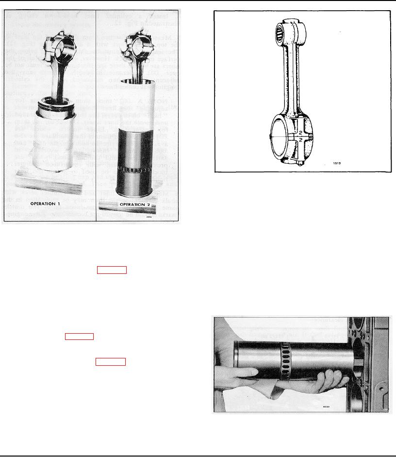
Fig. 14 - Typical Connecting Rod Markings
into the liner until the piston is free of the ring
compressor.
CAUTION: Do not force the piston into the
Fig. 13 - Installing Piston and Connecting Rod Assembly
liner. The peripheral abutment type expanders
in Ring Compressor and Cylinder Liner
apply considerably more force on the oil ring
than the standard expander. Therefore, extra
compressor. Then push the piston down until it contacts
care must be taken during the loading
the wood block (Operation I of Fig. 13).
operation to prevent ring breakage.
5. Note the position of the matchmark and place the
8. Remove the connecting rod cap and the ring
liner, with the flange end down, on the wood block.
compressor. Then push the piston down until the
compression rings pass the cylinder liner ports.
6. Place the ring compressor and the piston and
connecting rod assembly on the liner so the numbers on
the rod and cap are aligned with the matchmark on the
liner (Operation 2 of Fig. 13).
NOTE: The numbers on the side of the
connecting rod and cap (Fig. 14) identify the
rod with the cap and indicate the particular
cylinder in which they are used. If a new
service connecting rod is to be installed, the
same identification numbers must be stamped
in the same location as on the connecting rod
that was replaced.
Fig. 15 - Installing Piston, Rod and Liner
7. Push the piston and connecting rod assembly down
Assembly in Cylinder Block
Page 108