
TM 5-3810-300-24&P-3
BLOWER 3.4
The blower inlet screen should be inspected periodically,
as noted in Section 15.1, for an accumulation of dirt
which, after prolonged operation, may affect the air flow.
Servicing of the screen consists of thoroughly washing it
in fuel oil and cleaning with a stiff brush until the screen
is free of all the dirt deposits.
Remove Blower
In most cases, removal of the blower, together with the
governor drive, fresh water pump, fuel oil pump, and the
blower drive shaft cover, will be found most
advantageous. For removal of this assembly, refer to
Figs. 3 and 4 and proceed as follows:
1. Drain the cooling system.
2. Remove the governor control housing assembly
as outlined under "Remove Governor" in Section 2.7.1
for a limiting speed governor.
3. Disconnect the fuel lines at the fuel pump.
4. Loosen the water pump connections at the
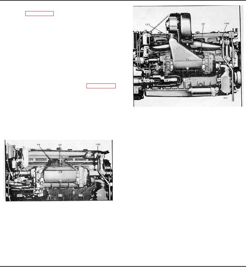
Fig. 4 - Typical Blower Mounting (71T Engine)
pump cover (inlet) and the cylinder block.
33
Cover--Blower Drive
100 Governor
Shaft
101 Pump--Fuel
48 Support--Blower Drive
114 Clamp--Blower
7. If the engine is equipped with a manual
Gear Hub
Drive Cover Seal
operating shut-down, disconnect the Bowden wire from
63 Bolt--Blower Mounting
122 Hose--Air Inlet
78 Housing--Air Inlet
123 Clamp--Hose
99 Pump--Fresh Water
the air shut-down valve shaft lever, then remove the bolt
securing the Bowden wire clip to the air shut-down
housing.
8. Remove the air cleaner (non-turboed engines),
then remove the air inlet housing, gasket, striker plate
and air inlet screen from the blower.
9. Remove the blower drive shaft as outlined in
Section 1.7.6.
10. Loosen the blower drive shaft cover seal clamp
(114) at the blower drive gear hub support.
Fig. 3 - Typical Blower Mounting (71 Engine)
11. Remove the bolts and plain washers securing
2
Housing--Blower
100 Governor
the blower to the cylinder block. Slide the blower slightly
33
Cover--Blower Drive Shaft
101 Pump--Fuel
forward, withdraw the blower drive shaft cover from the
63
Bolt--Blower Mounting
114 Clamp--Blower
seal, then lift the blower away from the cylinder block.
78
Housing--Air Shut-down
Drive Cover Seal
Remove Accessories from Blower
99
Pump--Fresh Water
1. Remove the three bolts and seal washer
assemblies securing the fuel pump to the blower rear
end plate cover, then remove the fuel pump, gasket and
drive coupling fork.
PAGE 253