
14.3.2 LIMITING SPEED GOVERNOR ADJUSTMENT (DUEL RANGE)
1
Set the high maximum no-load speed.
b. Recheck the engine speed and readjust if
a. Start the engine and position the speed control
necessary.
lever in the maximum speed position.
b. Turn the low maximum speed adjustment screw
in until the high maximum speed desired is
obtained.
c. Stop the engine and remove the spring housing
assembly.
CAUTION: Do not permit the seal ring
on the piston to slide past the air inlet
port, since the seal ring will be
damaged.
d. Note the distance the piston is within the spring
housing when it is against the low maximum
speed screw, and then remove the sleeve from
the piston.
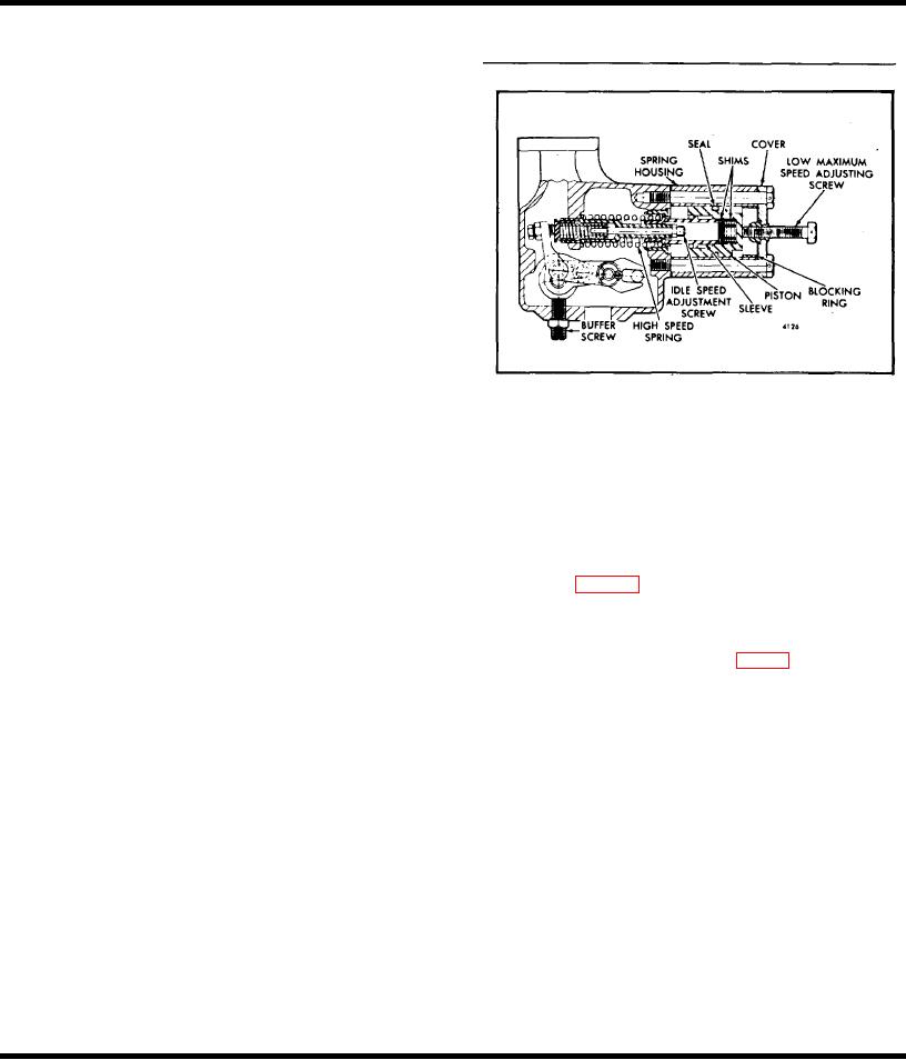
Fig. 6 Current Dual Range Governor
NOTE: When checking this distance,
3
Check both the high maximum and low maximum
the piston should be held tight against
engine speeds. Make any adjustment that is
the adjustment screw of the cover that is
necessary as outlined in Steps 1 and 2.
held in position, with its gasket, against
the end of the spring housing.
Adjust Idle Speed
With the maximum no-load speed properly adjusted, the
e. Remove a quantity of shims, from the shims
idle speed may be adjusted as follows:
within the piston, equal to the distance noted in
Step d.
1
Refer to Figs 5 and 6 and remove the spring
housing to uncover the idle speed adjusting screw.
f. Start the engine and position the engine speed
control lever in the maximum speed position and
2
With the engine at normal operating temperature
apply air pressure to the governor and note the
and with the buffer screw, Fig 6, backed out to
engine speed.
avoid contact with the differential lever, engine is
operating at approximately 15 rpm below the
g. Remove the air pressure from the governor and
recommended idle speed.
stop the engine, then install or remove shims as
The recommended idle speed is 450 rpm but may
required to obtain the correct high maximum no-
vary with engine applications.
load speed. Removing shims will decrease the
engine speed and adding shims will increase the
3
Hold the idle screw and tighten the lock nut.
engine speed.
4
Install the high speed spring retainer and retain with
NOTE: Each .010" shim removed or
the two bolts.
added will decrease or increase the
engine speed approximately 10 rpm.
Adjust Buffer Screw
With the idle speed set, the buffer screw may be
2
Set the low maximum no-load engine speed.
adjusted as follows:
a. Adjust the low maximum speed adjusting screw,
1
With the engine running at normal operating
with the speed control lever held in the maximum
temperature, turn the buffer screw in so that it
speed position, until the desired low maximum is
contacts the differential lever as lightly as possible
obtained. Turn the screw in to increase or out to
and still eliminates the engine roll.
decrease the engine speed.
Page 398