
PROPEL TRANSMISSION
SUBSECTION 9B
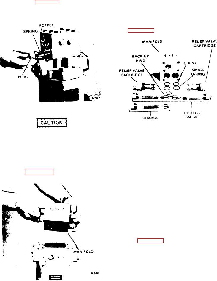
up rings on top of the O-rings. These back-up rings are
3. To remove the charge relief valve, remove the plug,
rectangular in cross section and slightly cupped on one
spring and poppet (see Figure 9B-24). If any shims fall out of
side where they mate with the O-ring.
the plug, be sure to reinstall them.
B. The charge relief valve, high pressure relief valves, and
the shuttle valve can now be removed and reinstalled as
given in steps 1, 2 and 3 if they were not removed yet
(see Figure 9B-26).
Figure 9B-24. Charge Relief Valve Removal
Do not lose any of the shims inside the plug.
Figure 9B-26. Manifold and Valves
Reinstall the valve by inserting the poppet, spring and plug.
4. The manifold can be removed and replaced as an as-
C. Install the smaller O-ring in the port with the full coun-
sembly without removing any of the valves or it can be re-
terbore. The other O-rings and back-up rings fit in the
moved after all the valves have been removed. To remove
ports with the machined grooves. The O-rings should be
and reinstall the manifold, proceed as follows.
installed first, then the back-up ring (concave groove
A. Remove the capscrews and lift the manifold off the
faces the O-ring).
motor (see Figure 9B-25). The three ports are sealed
D. Install the manifold on the motor checking that the back-
with O-rings and the two adjacent ports also have back-
up rings and O-rings remain in place. Install the cap-
screws and tighten to 16-21 ft-lbs.
4. Connect the high pressure lines and the case drain line.
5. Perform the start-up procedure described at the be-
ginning of this subsection.
INSTALLATION
Care must be exercised when installing a new or over-
hauled motor to prevent misalignment, which can lead to
excessive motor wear. Install a new or overhauled motor as
follows (see Figure 9B-21).
1. Check the brake plate, the pilot bore diameter on the
motor, the splined couplings on the brake, and the splined
motor output shaft for burrsor imperfections that could pre-
vent the motor from seating properly on the brake plate.
Carefully remove any imprefections by lapping.
2. Apply a slight amount of grease to the pilot diameters
and the shaft splines. Apply sealing compound (21Z587-
D4) to the mating surfaces of the brake plate and motor.
Figure 9B-25. Manifold Removal
9B-14