
SUBSECTION 1OA
ELECTRICAL SYSTEMS
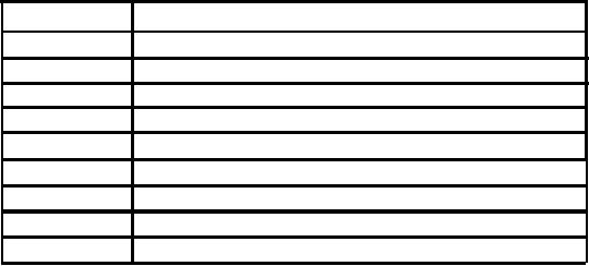
helpful in determining the cause of an electrical malfunc-
GENERAL
tion. Table 10A-1 lists the circuit breakers and the circuits
This subsection contains schematics of the power plant,
that are controlled by them. There is one circuit breaker
floodlights, mark-load system, and the main machinery (see
located at the right rear side of the engine, the other circuit
Figures 10A-1 and 10A-2). These schematics should be
breakers are located in the operator's module.
Table 10A-1. Circuit Breakers
BREAKER
CIRCUITS CONTROLLED
CB-1 (Engine)
Engine
CB-1
Clutch, boom hoist, start aid, horn
Main drum pawls, swing brake, gauges, lights
CB-2
CB-3
Windshield wipers
CB-4
Heater, defogger
CB-5
Drum turn indicator, load monitoring
Engine warning,.spares
CB-6
CB-7
Propel, swing
CB-8
Spare
1OA-1