
2. Note connections as shown. To make
s t a t o r a n d d i o d e c h e c k s , remove t h e
three nuts, three regulator leads, three
stator leads, six diode leads and the (R)
terminal lead from the three studs.
3. To make field coil checks, disconnect
the
two field coil leads from the
regulator.
4 . See " B e a r i n g R e p l a c e m e n t " o n p a g e
10D-16 for information on separating the
drive end frame assembly from the recti-
fier and frame assembly.
FIELD COIL CHECKS.
To check for
grounds, connect a test lamp, or an
ohmmeter to one field coil lead and to the
end frame as shown in Figure 10D-15 on
If the lamp lights, or if
page 10D-13.
ohmmeter reading is low, the field coil is
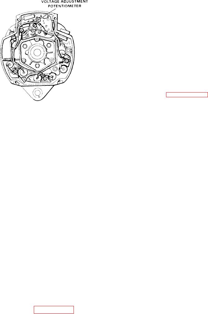
SILASTIC COATING NOT
grounded.
SHOWN ON REGULATOR
To check for opens. connect a test lamp
Figure 10D-13. Adjusting Voltage
or an ohmmeter to the two field coil leads
Setting
If the lamp fails to light, or
as shown.
if ohmmeter reading is high, the field
justing screw will show no change on the
c o i l is open.
However, turning the adjust-
ing screw will change the voltage setting
checked
for
The
winding
is
to a new value, which will be indicated
short-circuits by connecting a battery
by the voltmeter when the battery state
and ammeter in series with the field coil.
of charge increases.
Note the ammeter reading and the spec-
ifications
stamped on
the alternator
RemovaI
An ammeter reading above the
frame.
specified value indicates shorted wind-
To remove the alternator, proceed as fol-
An alternate method is to check
ings.
lows:
the resistance of the field by connecting
an ohmmeter to the field coil. If the re-
1. Disconnect the battery cables. Re-
sistance reading is below the specified
move the electrical lead at the alternator.
value, the winding is shorted. The spe-
cified resistance value can be determined
2. Loosen the mounting bolts and the ad-
by dividing the voltage by the current.
justing strap bolt. Swing the alternator
down and remove the drive belts.
To replace the field coil, separate drive
end frame, remove field coil attaching
3. Support the alternator and remove the
pull leads and grommet
and
screws
Re-
adjusting strap bolt and washers.
through end frame hole. Place grease on
move the mounting bolts, washers and
grommet and pull grommet into hole dur-
n u t s . Remove the alternator.
i n g assembly.
4. Remove the pulley assembly from the
Check each of the six
DIODE CHECKS.
alternator.
diodes by removing each diode lead from
the stud and connecting an ohmmeter us-
ing the lowest range scale to the diode
Repair and Test
l e a d and case. T h e n r e v e r s e t h e o h m m e -
ter lead connection to the diode lead and
To disassemble the al-
DISASSEMBLY.
If both reading are the same, re-
case.
ternator, proceed as follows:
place the diode. A good diode will give
o n e high and one low reading.
1. Remove the cover plate, cover and
With the cover off components
gasket .
look as shown in Figure 10D-14 on page
10D-13.