be replaced and the end of the crank-
Inspect Vibration Damper
shaft
Check the outside
refinished.
diameter of the inner cone for wear at
After Removal, clean the vibration damp-
the crankshaft front oil seal contact sur-
er in fuel oil and dry it with compressed
face.
I f w o r n , replace the oil seal and
air.
cone.
Examine the viscous type damper for
A loose engine mount could damage the
d e n t s , n i c k s , fluid leakage or bulges in
vibration damper by allowing the engine
the outer casing of the damper. Any in-
move
slightly
during
operation.
to
dications of the above are sufficient
Therefore, it is good practice to period-
cause for replacing the damper. Due to
ically inspect the engine mounts to be
the close clearances between the internal
sure they are not loose, cracked or dete-
flywheel and outer casing, dents may
riorated.
render the damper ineffective. Bulges
or splits indicate the fluid has ignited
and expansion of the resultant gases has
I n s t a l l Vibration Damper on Crankshaft
bulged or forced the casing open at its
crimped edges.
Refer to Figure 11B-99 on page 11B-63
for relative location of the parts and as-
S i n c e the viscous type damper is a preci-
s e m b l e as follows:
sion built closely fitted and sealed
device, it is not possible to repair it.
1 . Coat the lip of the oil seal in the front
cover lightly with cup grease or vegeta-
Regardless of condition, the viscous type
ble shortening and lubricate the sleeve
damper should be replaced at time of
and spacer if used, with engine oil.
normal periodic major engine overhaul.
2. Slide the sleeve, if used, over the
If damage to the vibration damper is ex-
large diameter o f t h e c r a n k s h a f t a n d
tensive, inspect the crankshaft. A loose
against the oil slinger, being sure the
or defective vibration damper, after ex-
slinger i s t i g h t a g a i n s t t h e o i l p u m p
tended operation, may result in a
drive gear; then slide the spacer against
cracked crankshaft.
t h e sleeve.
Inspect the damper spacer cones, hub,
3. With the Woodruff keys (if used) in
sleeve and the end of the crankshaft for
place, slide the inner cone, with the ta-
galling or burrs.
Slight scratches or
pered end pointing to the front of the
burrs may be removed with emery cloth.
next to the oil slinger or
crankshaft,
If seriously damaged, the parts should
against the spacer, if used.
NOTE
When the vibration damper and
crankshaft pulley are bolted to-
gether and mounted on the front
the
crankshaft
(see
end
of
extra precaution should be taken
to be certain that the inner cone
does not prematurely clamp to the
crankshaft.
4. Slide the damper and hub as an as-
sembly--long end of the hub facing the
crankshaft cover--into position.
NOTE
Do not hit a viscous type damper
w i t h a hammer to position it on the
crankshaft.
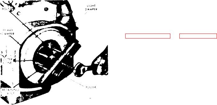
F i g u r e 11B-100. L o o s e n i n g V i b r a t i o n
Damper Outer Cone

