
on the ring. The ends of the ring must
remain s q u a r e a n d t h e c h a m f e r o n t h e
approximately
must be
edge
outer
0.015".
Check the ring side clearance as shown
i n Figure 11B-123 on page 11B-77.
Install Piston Rings
NOTE
Lubricate the piston rings and pis-
ton with engine oil before instal-
ling the rings.
Starting with the bottom ring, install
the compression rings with tool J 8128
as s h o w n i n F i g u r e 1 1 B - 1 1 3 o n p a g e
To avoid breaking or over-
11B-72.
stressing the rings, do not spread
them any more than necessary to slip
Refer to
them o v e r t h e p i s t o n .
Figure 11B-124 on page 11B-77 for
ring identification.
1. Stagger the ring gaps around the pis-
ton.
to
Figure
11B-124
on
2. Refer
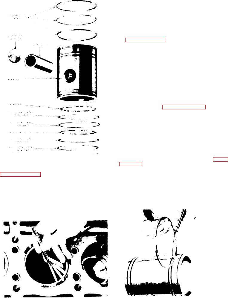
Figure 11B-121. Piston Ring Location
11B-77 for the type and location and in-
s t a l l the oil control rings as follows:
with
a
feeler
guage
as
shown
in
F i g u r e 11B-122 on page 11B-76.
A. lnstall the ring expanders in the oil
control ring grooves in the piston
If the gap on a compression ring is in-
s k i r t . When installing the oil control
sufficient, it may be increased by filing
use care to prevent overlap-
rings,
or stoning the ends of the ring. File or
ping the ends of ring expanders. An
stone both ends of the ring so the cut-
overlapped expander will cause the oil
ting action is from the outer surface to
the inner surface. This will prevent any
chipping or peeling of the chrome plate
F i g u r e 11B-123. Measuring Pi ston
F i g u r e 11B-122. Measuring Piston
R i n g Side Clearance
Ring Gap