
Figure 11B-148. Woodruff Keys for
Camshafts
forced through the milled slots in the
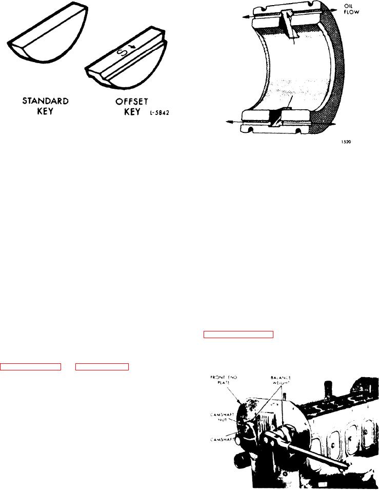
Figure 11B-149. Camshaft
bearing and then out the grooves to fur-
Intermediate Bearing
nish additional oil to the cam follower
rollers.
This permits the cam pocket to
and balance shaft drive gears at the rear
be filled rapidly to the operating oil level
of the engine.
immediately after starting the engine.
7. Remove the gear nut retaining plates.
R e m o v e Camshaft or Balance Shaft
8. Remove the gear retaining nuts on the
gear end of the camshaft and the balance
Whenever an engine is being completely
shaft.
Remove the nut and lock washer
reconditioned or the camshaft, gears,
from the balance weight end of each
bearings or thrust washers need replace-
shaft.
ing, remove the shafts from the engine
as follows:
9. Remove the front balance weights.
1. Drain the engine cooling system.
10. Remove the lock screws that secure
the camshaft intermediate bearings.
2. Remove all of the accessories and as-
semblies necessary to facilitate mounting
11. Rotate the gears as required to re-
the engine on an overhaul stand.
veal the end bearing retaining bolts.
Remove
the
bolts
as
shown
in
3. Mount the engine on an overhaul
F i g u r e 11B-151 on page 11B-98.
stand.
Be sure the engine is securely
mounted on the overhaul stand before re-
leasing
the
lifting
sling
(see
4. Remove the cylinder head.
5. Remove
the flywheel and flywheel
housing.
6. Remove the front balance weight cover
and place a wood block between the bal-
ance weights (see Figure 11B-150) or
wedge a clean rag between the camshaft
F i g u r e 11B-150. Loosening Nut on
Camshaft or Balance Shaft
E n g i n e (Less Major Assemblies)