
4. Remove the camshaft gear puller, spa-
Finger tighten
cers and adaptor plate.
the gear retaining nut on the shaft.
5. Install the front end bearing with the
Tighten the
bolts and lockwashers.
bolts to 35-40 lb-ft (47-54 Nm) torque.
6. Install the balance weight on the front
end of the camshaft.
7. Start the balance weight retaining nut
camshaft
and
lockwasher on
the
Place a wood block between the balance
weights ( F i g u r e 1 1 B - 1 5 0 o n p a g e
Tighten the gear retaining nut
11B-97).
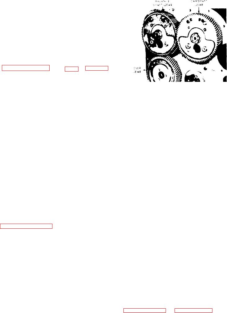
F i g u r e 11B-159. Camshaft and Balance
and the balance weight nut to 300-325
S h a f t Gears
lb-ft (407-441 Nm) torque.
"R" for right hand rotation engine) are
8. Align the holes in the camshaft inter-
located on either the camshaft gear or
mediate bearings with the tapped holes in
Install
balance shaft gear and the mating idler
the top of the cylinder block.
and tighten the lock screws to 15-20
gear.
lb-ft (20-27 Nm) torque.
The camshaft and balance shaft gears are
keyed to their respective shafts and held
9. Reinstall the parts, accessories and
securely against t h e s h o u l d e r o n t h e
assemblies that were removed from the
A gear nut retainer,
shaft by a nut.
engine as outlined in their respective
with a
double
hexagon
hole
in
the
subsections of this section.
center, f i t s o v e r t h e n u t a n d p r e v e n t
loosening of the nut. The retainer is at-
1 0 . Refill the cooling system.
tached to the gear by bolts threaded into
tapped holes in the gear. These tapped
holes are also utilized in mounting an ac-
CAMSHAFT AND BALANCE SHAFT
cessory drive on the camshaft or balance
GEARS
shaft gear.
A small balance weight is attached to the
Description
inner face of each gear. These weights
are important in maintaining perfect en-
gine balance.
The camshaft and balance shaft gears,
l o c a t e d at
the
flywheel
end
of
the
engine, mesh with each other and run at
R e m o v e Camshaft and Balance Shaft
the same speed as the crankshaft (see
Either
one
of
the
Gears
gears may be driven from the crankshaft
1. Remove t h e c a m s h a f t a n d b a l a n c e
timing gear, through an idle gear, de-
shaft from the engine as outlined in "Re-
Viewing
pending upon engine rotation.
move Camshaft or Balance Shaft" on page
the engine from the flywheel or gear
11B-97.
train end, the right hand gear has left
hand helical teeth and the left hand gear
2. Support the camshaft suitably in the
has right hand helical teeth. The idler
soft jaws of a bench vice, being careful
gear mates with the left hand gear.
n o t to damage the cams.
Since the camshaft and balance shaft
3. Remove the nut retaining the gear on
gears must be in time with each other,
the camshaft.
t h e l e t t e r "O" is stamped on one tooth of
one of the gears with a corresponding
4. Back out the puller screw of tool J
mark at the root of the mating tooth of
1902-01 and attach the puller to the out-
Also, since these two
the other gear.
er face of the gear with four bolts (see
gears as a unit must be in time with the
identification marks (letter
crankshaft,