
locations.
The washers seat in 7/8" spot
faces a t t h e f l y w h e e l h o u s i n g a t t a c h i n g
bolt holes, thus preventing oil leakage at
t h e s e locations.
Remove Idler Gear (Flywheel Housing
P r e v i o u s l y Removed)
1. Remove the idler gear hub to cylinder
block bolt and washer and withdraw the
assembly from the cylinder block rear
end plate.
NOTE
Before removing the idler gear
check the idler gear, hub and
bearing assembly for any percepti-
ble wobble or shake when pressure
is applied; by firmly grasping the
rim of the gear with both hands
and rocking in relation to the bear-
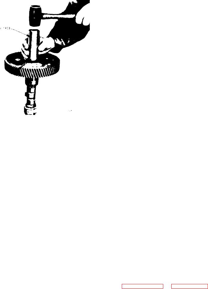
Figure 11B-161. Replacing
Camshaft
The bearing m u s t b e r e -
ing.
placed i f t h e g e a r w o b b l e s o r
Gear
shakes.
If the gear assembly is
it is only necessary
satisfactory,
t u r n , is supported on a stationary hub.
to check the pre-load before rein-
This hub is secured directly to the cyl-
stallation.
inder block by a bolt which passes
through the hub and rear end plate. A
hollow dowel serves a two-fold purpose;
2. Remove the idler gear hole spacer in
first, as a locating dowel it positions the
the same manner if the engine is being
hub and prevents it from rotating and,
completely reconditioned.
second, conducts oil under pressure
from an oil gallery in the cylinder block
through a passage in the gear hub to the
D i s a s s e m b l e Idler Gear Assembly
roller bearing.
While removing or installing an idler gear
The idler gear bearing consists of two
bearing, the bearing MUST be rotated to
cups, two cones and an outer and inner
avoid the possibility of damaging the
spacer ring.
bearing by brinelling the bearing cones.
Brinelling refers to the marking of the
The inner and outer cones of the idler
cones by applying a heavy load through
gear bearing are pressed onto the gear
the rollers of a non-rotating bearing in
hub and, therefore, do not rotate. Spa-
such a way that the rollers leave im-
a spacer, s e p a r a t e t h e
c e r rings
or
pressions on the contact surfaces of the
The bearing cup(s) has a light
cones.
These impressions may not be
cones.
press f i t i n t h e i d l e r g e a r a n d i s h e l d
discerned
normal
easily
during
against a flanged lip inside the idler gear
For example, a bearing may
inspection.
on one side and by a bearing retainer
be brinelled if a load were applied to the
secured with six bolts and three bolt
inner cone of the bearing assembly in
l o c k s on the other side.
order to force the outer cone into the
idler gear bore, thus transmitting the
An idler gear hole spacer (dummy hub)
force through the bearing rollers. A
is used on the side opposite the idler
brinelled bearing may have a very short
NO gasket is used between the
gear.
life.
idler gear hub or dummy hub and the
flywheel housing. The flywheel housing
Refer to Figure 11B-163 on page 11B-108
bears against the inner races of the idler
for the location and identification of
gear bearing and also against the dummy
parts and disassemble the bearing as fol-
hub. Three self-locking bolts and steel
lows:
washers are used to attach the flywheel
housing at the idler gear and dummy hub