
Refer to
tester J 22396.
freeness
Figure 11C-9 and place the handle on top
of the injector follower.
I f n e c e s s a r y , a d j u s t the contact screw in
t h e handle to ensure the contact screw is
at the center of the follower when the
follower spring is compressed.
With the injector control rack held in the
no-fuel position, push the handle down
and depress the follower to the bottom of
its stroke. Then very slowly release the
pressure on the handle while moving the
control rack up and down as shown in
Figure 11C-9 on page 11C-6 until the
If
F i g u r e 11C-10. Removing Injector
follwer reaches the top of its travel.
Follower Stop Pin
the rack does not fall freely, loosen the
injector nut, turn the tip, then retighten
INSTALLING FUEL INJECTOR IN TEST-
t h e n u t . Loosen and retighten the nut a
ER J 23010
couple of times if necessary. Generally
this will free the rack.
Then, if the
r a c k i s n o t f r e e , c h a n g e t h e injector
1. Select the proper clamping head
n u t . I n some cases it may be necessary
(Figure 11C-12 on
page
11C-8).
Position
to disassemble the injector to eliminate
it on the clamping post and tighten the
t h e cause of the misaligned parts.
thumb screw into the lower detent posi-
t i o n (see Figure 11C-13 on page 11C-8).
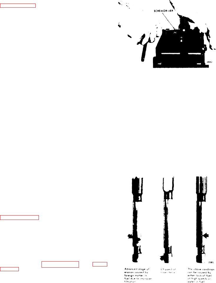
VISUAL INSPECTION OF PLUNGER. An
2. Connect the test oil delivery piping
injector which passes all of the previous
into the clamping head.
tests should have the plunger checked
visually, under a magnifying glass, f o r
3. Connect the test oil clear discharge
excessive wear or a possible chip on the
bottom helix.
tubing onto the pipe on the clamping
There is a small area on
the bottom helix and lower portion of the
upper helix, if chipped, that will not be
indicated in any of the tests.
4. Locate the adaptor plate on top of the
support bracket by positioning the 3/8"
Remove the plunger from the injector as
follows:
1. Supprt the injector, right side up, in
h o l d i n g fixture J 22396.
2. Compress the follower spring. Then
raise the spring above the stop pin with
a screw driver and withdraw the pin (see
Figure 11C-10). Allow the spring to rise
gradually.
3. Remove the injector from the holding
fixture. Turn the injector upside down,
to prevent the entry of dirt, and catch
the spring and plunger as they drop
out.
4. Inspect the plunger.
If the plunger
i s chipped
(
on
11C-8), replace the plunger and bushing
assembly.
5. Reinstall the plunger, follower and
Figure 11C-11. Unusable Injector
spring.
Plungers
Fuel System and Governor
11C-7