
2. Move lever 5 down to release the
clamping pressure.
3. Swing out the adaptor plate and re-
move the injector after the nylon seals in
the clamping head are free and clear of
the injector filter caps.
4. Carefully return lever 5 to the up
(horizontal) position.
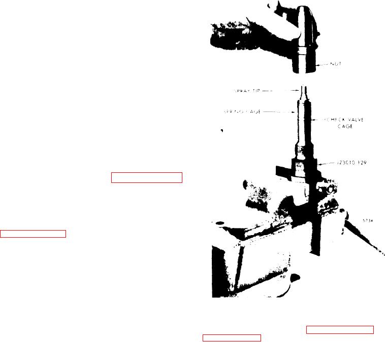
NEEDLE VALVE TIP TEST. Assemble in-
jector parts on tip test adaptor as
follows:
1. Clamp the flat sides of the tip test
adaptor J 23010-129 firmly in a vise and
assemble the cleaned injector parts in-
cluding the check valve cage, spring,
spring seat, spring cage and spray tip
assembly.
2. Carefully pilot the injector nut over
the spray tip and valve parts and thread
it onto the adaptor (see Figure 11C-15).
3. Tighten the injector nut.
4. Mount the adaptor and assembled in-
jector parts in the support bracket (a-
daptor plate not needed). Refer to
Figure 11C-16 on page 11C-11.
5. Install the offset clamping head on the
clamping post (on J 23010 testers without
serial numbers, use the upper detent po-
sition and on J 23010 testers numbered
1051 and higher, use the lower detent
position).
6. Select the (larger) 9/16"-18 threaded
Figure 11C-15. Injector on Tip Test
coupling nut J 23010-20 and thread it on
Adaptor
t u b i n g J 23010-167.
end of the adaptor (see Figure 11C-16 on
Install the tubing and fitting to adaptor
J 23010-167.
NOTE
7. Connect the tubing to tip test adaptor
Use the fuel injector clamping pro-
J 23010-129 by threading the coupling
cedure
to
clamp
adaptor
J
nut on the tip test adaptor.
2 3 0 1 0 - 1 6 7 in the injector tester.
INSTALLING ADAPTOR AND TUBE ON
TESTER
SPRAY TIP TEST
1. Position the adaptor and tubing as-
1, Move lever 4 down and operate the
sembly with the solid projecting end lo-
pump lever 1 rapidly with smooth even
cated in the hole on the left side of the
strokes (40 strokes per minute) simulat-
support bracket.
ing the action of the tip functioning in
the engine (see Figure 11C-14 on page
2. Swing the clamping head over the
11C-9).
adaptor and clamp it with the oil supply
outlet aligned over the open projecting
11C-10