
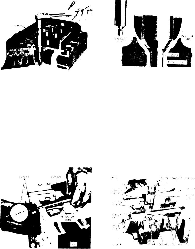
Figure 11C-46. Reaming Injector Tube
Figure 11C-48. Measuring
f o r Injector Nut
Relationship of Gauge to Fire Deck
press air. Then perform the second
casionally to observe the reaming
reaming operation as follows:
progress.
A. Place a few drops of cutting oil on the
D. R e m o v e t h e c h i p s f r o m t h e i n j e c t o r
bevel seat of the tube. Carefully
tube and, using gauge J 25521, con-
lower reamer J 5286-9 into the injector
tinue the reaming operation until the
tube until it contacts the bevel seat.
shoulder of the spray tip is flush to
0.014" with the fire deck of the cyl-
B. Make a trial cut by turning the ream-
inder
head
shown
in
er steadily without applying any
Figure
11C-48.
Then
wash
the
inte-
downward force on the reamer. Re-
rior of the injector tube with clean
move the reamer, blow out the chips
solvent and dry it with compressed
and look at the bevel seat to see what
air.
portion of the seat has been cut.
C. Proceed carefully with the reaming
F U E L PUMP
operation, withdrawing the reamer oc-
Figure 11C-47. Measuring Injector
Figure 11C-49. Typical Fuel Pump
Seat Bevel Seat
Fuel System and Governor
11C-27