
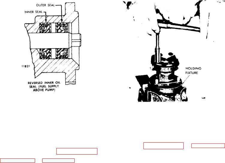
Figure 11C-52. Fuel Pump Oil Seal
Figure 11C-53. Removing Pump Cover
4. Check the drive coupling fork and, if
broken or worn, replace it with a new
6. Remove the valve spring, pin and re-
coupling.
lief valve from the valve cavity in the
pump body.
D i s a s s e m b l e Fuel Pump
7. If the oil seals need replacing, remove
them with oil seal remover J
With the fuel pump removed from the en-
1508-13 (Figure 11C-54 on page 11C-31).
gine and mounted in holding fixture J
Clamp the pump body in a bench vise
1508-10 as shown in Figure 11C-53, refer
and tap the end of the tool with a ham-
to Figure 11C-49 on page 11C-27 end
mer to remove the outer and inner seals.
Figure 11C-55 on page 11C-31 and disas-
semble the pump as follows:
NOTE
1. Remove the eight cover bolts and
Observe the position of the oil seal
withdraw the pump cover from the pump
lips before removing the old seals
body. Use care not to damage the fin-
to permit installation of the new
ished faces of the pump body and cover.
s e a l s in the same position.
2. Withdraw the drive shaft, drive gear
and gear retaining ball as an assembly
from the pump body.
Inspection
3. Press the drive shaft just far enough
Clean all of the parts in clean fuel oil
to remove the steel locking ball. Then
and dry them with compressed air.
invert the shaft and gear assembly and
press the shaft from the gear. Do not
Oil seals, once removed from the pump
misplace the steel ball. Do not press the
squared end of the shaft through the
body, must be discarded and replaced
w i t h new seals.
gear as slight score marks will damage
the oil seal contact surface.
Check the pump gear teeth for scoring,
chipping or wear. Check the ball slot in
4. Remove the driven shaft and gear as
the drive gear for wear. If necessary,
an assembly from the pump body. DO
replace the gear.
not remove the gear from the shaft. The
driven gear and shaft are serviced only
Inspect the drive and driven shafts for
a s an assembly.
scoring or wear. Replace the shafts if
necessary. The driven shaft is serviced
5. Remove the relief valve plug and cop-
a s a gear and shaft assembly only.
per gasket,