
ther event, the pump must be tightened
Install Oil Pump
on the bearing cap before the clearance
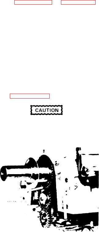
Refer to Figure 11E-3 on page 11E-4 and
b e t w e e n the gear teeth is measured.
install the oil pump on the main bearing
caps as follows:
NOTE
When
1. Hold the pump assembly against the
adjusting for gear tooth
main bearing caps so the idler gear (56)
clearance by installing or removing
meshes w i t h t h e d r i v i n g g e a r o n t h e
shims, the same number of shims
crankshaft.
must be changed under each foot
so that the pump will always be
2. Insert the four bolts (55) with lock
level on the main bearing caps.
washers through the mounting feet of the
The insertion or removal of one
pump and into the bearing caps (39).
0.005" shim will change the gear
tooth clearance by 0.0035".
Align the pump so that the teeth of
crankshaft gear and idler gear are paral-
lel; t h e n t i g h t e n t h e b o l t s t o 3 5 - 3 9 l b - f t
and check clearance between the gear
3. Place a new gasket (76) between the
teeth with a feeler gage. Proper clear-
outlet pipe and the pressure regulator
ance between the crankshaft gear and
and bolt the two parts together loosely.
idler gear is 0.005" minimum, 0.012" max-
Use a new gasket (35) and secure the
imum (Figure 11E-11).
outlet pipe (15) to the oil pump body (3)
with the bolts not over 7.8" long. At-
tach the pressure regulator (68) to the
cylinder block using a new gasket (70).
Always check the clearance be-
When attaching the pump outlet and the
tween the crankshaft gear and the
pressure regulator, none of the bolts
oil pump idler gear with the engine
should be tightened until all the bolts
in the upright or running position.
have been started. After all bolts are
started, the outlet pipe bolts (57) should
be tightened alternately, then the pres-
sure r e g u l a t o r b o l t s ( 7 1 ) s h o u l d b e
tightened,
and
finally
the
pipe-to-regulator bolts (77) should be
secured. This procedure prevents twist-
ing the outlet pipe.
4. Attach the pump screen brackets (18)
to the main bearing caps with lock wash-
ers and bolts (58). Do not tighten the
bolts.
5. Affix a new gasket (27) to the pump
end of the inlet pipe (19), then attach
t h e pipe to the oil pump.
6. Set the screen cover (17) over the
outer end of the oil inlet pipe (19) and
secure it to the pipe and brackets (18)
F i g u r e 11E-11. Measuring Clearance
with bolts (64) washer, lock washers,
and n u t s ( 6 5 ) .
Tighten the bracket
B e t w e e n Teeth of Oil Pump Gears
bolts (58) to the bearing caps.
If the shims were used between the pump
7. Place the screen (2) in the cover (17)
mounting feet and the bearing caps and
and lock it in place with retainer (16).
new gears are not installed, the same
shims (cleaned) or the same number of
8. Recheck all bolts for tightness to as-
new (identical) shims should be installed
sure there will be no leaks in the oil
and the number then adjusted to obtain
pump and pipe mounting connections.
the proper clearance between gear teeth.
However, i f n e w g e a r s h a v e b e e n i n -
9. Place a new gasket on the oil pan and
n u m b e r o f shims w i l l b e
stalled, a
install the oil pan on the cylinder block.
r e q u i r e d u n d e r t h e m o u n t i n g f e e t . In ei-
L u b r i c a t i o n System