TM5-3810-305-10
3.
4.
Disconnect the drive shaft by removing four
capscrews and two caps (Figure 4-59). The
driveshaft must be disconnected from the
front axle and secured to a frame crossmem-
ber to prevent it from contacting the rotating
axle input yoke or the ground while the
vehicle is being towed. The spider bearing
caps must be taped or wired together to
prevent them from falling off and being lost.
Place the two-wheel/four-wheel drive shift
lever, located at the right of the operator’s
seat, in the two wheel drive position to pre-
vent damage to the transmission during
towing.
CAUTION
The tow bar MS500048 is the
only tow bar to be used on this
vehicle. If not available, see or-
ganizational maintenance. Fail-
ure to follow this procedure
could cause damage to equip-
ment.
5.
6.
Attach tow bar to the lugs on the outrigger
and to towing vehicle.
Release the parking brake in the operator’s
cab by pulling the lever up to release it. If the
vehicle’s electrical power is available, turn on
the emergency four-way flashers.
The crane may now be towed at speeds up to
20 mph (32 km/h) (depending on existing
conditions) for whatever distance is neces-
sary. When making turns, make them as wide
as possible (no sharp turns) at no more than 5
mph (8 km/h).
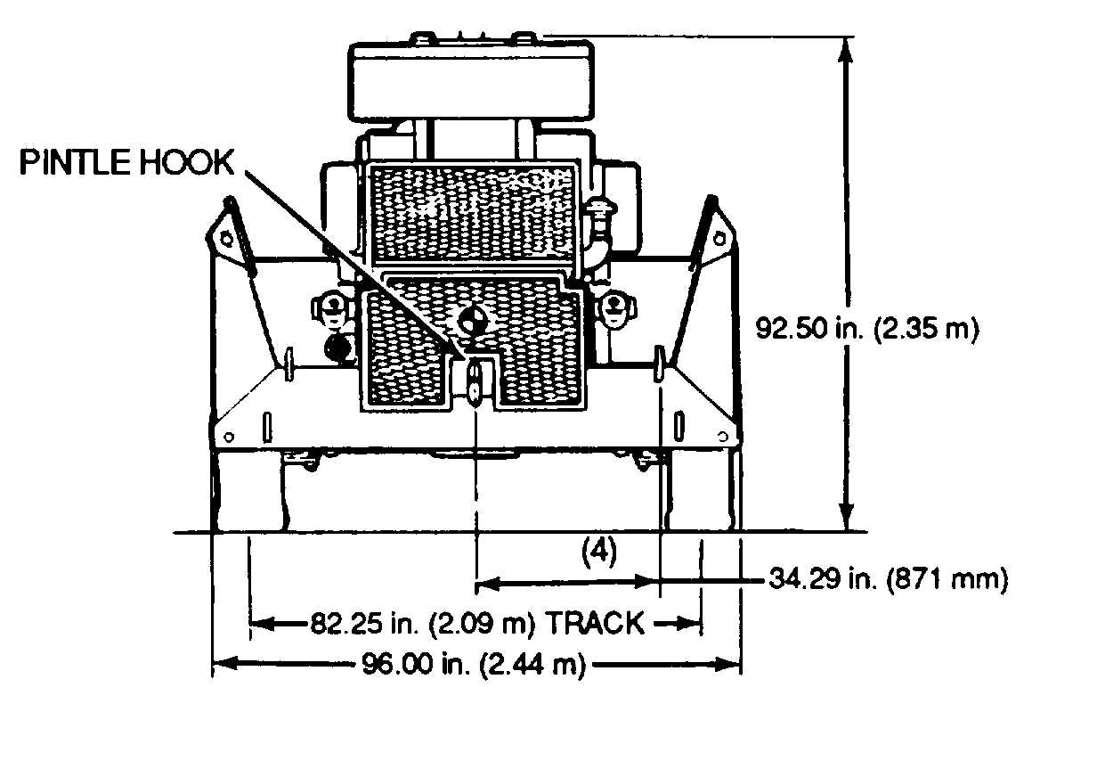
Figure 4-60. Preperation for Travel
4-73


