
TM 5-3810-305-23
0047
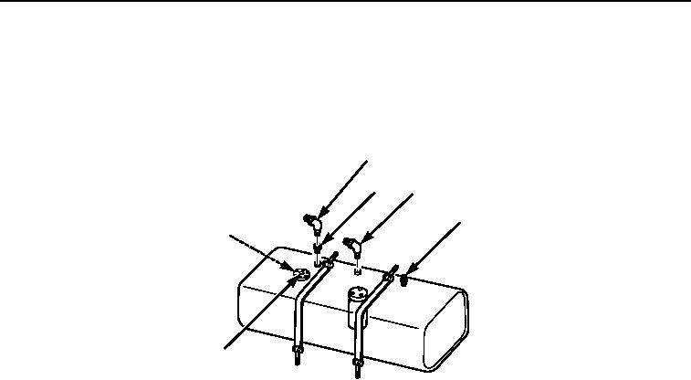
ASSEMBLY - Continued
3.
Install sending unit (Figure 6, Item 5), new gasket, four new lockwashers (Figure 6, Item 7), and machine
screws (Figure 6, Item 6) on fuel tank.
4.
Install check valve (Figure 6, Item 4), bushing (Figure 6, Item 2), and elbows (Figure 6, Items 1 and 3).
1
2
3
4
6,7
5
M0267105
Figure 6.
Fuel Tank Assembly.
END OF TASK
03/15/2011Rel(1.8)root(maintwp)wpno(M00053)