
TM 5-3810-305-23
0125
ASSEMBLY - Continued
CAUTION
Be sure relief valve is located above the horizontal centerline for the intended application.
Oil leakage may occur if vent is positioned incorrectly.
9.
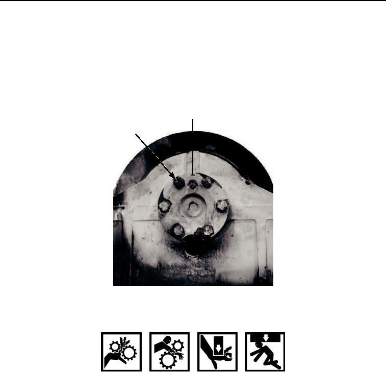
Install six new lockwashers (Figure 18, Item 2) and capscrews (Figure 18, Item 1) on bearing
support (Figure 18, Item 3).
3
1,2
M0665105
Figure 18. Bearing Support Fasteners Assembly.
WARNING
Weight of winch is approximately 300 lb (136 kg). Use adequate lifting equipment to lift and
support winch. DO NOT lift over personnel or let personnel walk underneath suspended load.
Failure to follow this warning may cause injury or death to personnel.
CAUTION
Snapring will keep output planet carrier correctly positioned in winch. Gear train damage may
occur if snapring is omitted.
10.
Stand winch on bearing support end and install snapring (Figure 19, Item 2) in bearing
support (Figure 19, Item 1).
03/15/2011Rel(1.8)root(maintwp)wpno(M00141)