
TM 5-3810-305-23
0150
ASSEMBLY
CAUTION
Two seal lips of U-cup seal must point toward inside of cylinder case, and wiper seal lips
must point toward outside of cylinder case. Use care to avoid nicking or scratching seal lips.
Failure to follow this caution may result in damage to equipment.
NOTE
Lubricate all parts with clean hydraulic oil.
1.
Install new U-cup seal (Figure 10, Item 2) and wiper (Figure 10, Item 3) in head gland (Figure 10, Item 1).
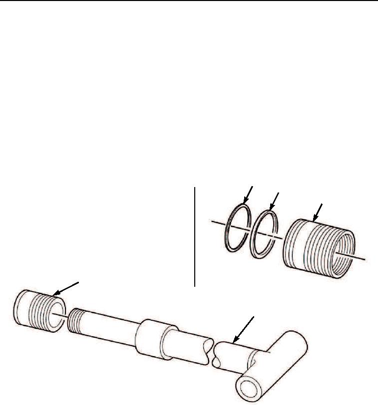
2.
Install new back-up ring (Figure 11, Item 4) and new o-ring (Figure 11, Item 3) on head gland
(Figure 11, Item 1) with new o-ring towards inside of cylinder case.
3.
Install head gland (Figure 11, Item 1) as an assembly on rod assembly (Figure 11, Item 2).
3
4
5
1
2
M0426105
Figure 11. Boom Extend Cylinder Assembly.
03/15/2011Rel(1.8)root(maintwp)wpno(M00166)