TM 5-3810-306-20
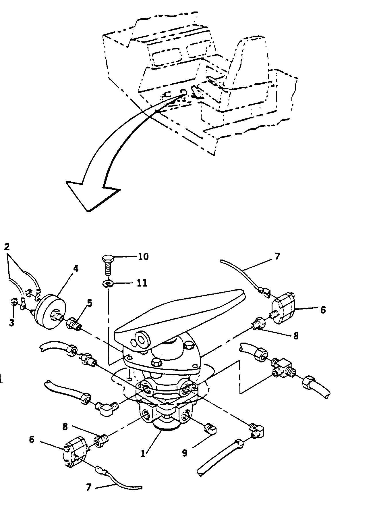
INSTALLATION:
1.
INSTALL FOOT BRAKE CONTROL VALVE (1).
a.
Align foot brake control valve (1) with cab floor
mounting
holes
and
securing
with
three
capscrews (10) and new lockwashers (11).
NOTE
Prior to installing fittings, hoses and
switches, coat threads with Loctite
#545.
b.
Install fittings on brake control valve.
c.
Remove tags, plugs and connect four air lines to
foot brake control valve.
2.
INSTALL STOP LIGHT SWITCH (4).
a.
Install fitting (5) and install stop light switch (4).
b.
Secure tagged electrical wires (2) with nuts (3).
3.
INSTALL
LOW
PRESSURE
INDICATOR
SWITCHES (6).
a.
Install fittings (8) and low pressure indicator
switches (6).
b.
Connect tagged electrical wires (7).
4.
CONNECT GROUND CABLE AT SHUNT. (REFER
TO PAGE 8-109.)
5.
START-UP ENGINE AND ALLOW AIR PRESSURE
TO BUILD UP. (REFER TO TM 5-3810-306-10.)
6.
CHECK
ALL
AIR
OPERATED
FUNCTIONS.
(REFER TO TM 5-3810-306-10.)
7.
INSTALL CAB BOTTOM PANEL. (REFER TO
PAGE 15-11.)
8.
INSTALL CAB FRONT PANEL. (REFER TO PAGE
15-10.)
END OF TASK
11-26